


15
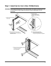
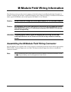
Step 5. Connect Field Wiring to Slot M4 & M5 M-Modules
If you installed M-Modules on either or both of the interior slots, the following instructions describe how to
secure the field wiring. If you did not install an M-Module in slots M4 or M5, skip this page and go to Step 6.
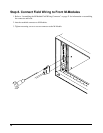
1. Cover the M0 2-row connector strip with provided Pin Protector/Cover (p.n. 1252-8273). This pin
protector protects the field wiring from chafing against the connector pins.
Note: Do not install the plastic cable hood (see page 21) on the field wiring connectors for the two internal
M-Modules. Do not install the RFI dress panels on the two interior M-Modules. If an RFI dress panel is
already installed on an M-Module, it must be removed. They are not needed and may interfere with
installation of the top shield.
2. Holes are provided in the Carrier for cable ties to secure the field wiring cables.
3. Install cable clamp plates (p.n. E2251-01203) on top side of PC board. Secure the cable clamp (but do not
overtighten). Both clamps are required to prevent damage to PC board.
4. To minimize RFI, install a dress panel (p.n. E2251-04301) over the front panel M0 slot position. Have
the dress panel machined or punched to allow the cable to pass through. Machine the cut as small as
possible; large enough for the cable and optional grommet (to prevent chafing) but tight to minimize RFI.
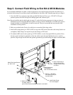
3. Secure field wiring to
through holes provided
on Carrier.
Carrier with wire ties
1. Place p.n. 1252-8273
Pin Protector over pins
to protect cable.
5. Machine Dress Panel
for ribbon cable or
punch Dress Panel and add grommet for round cable.
2. Attach field wiring
to M-Modules
with 4-40 Pozidrive screws.
4. Install Cable Clamp.
Do not overtighten.
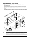
M3x20 Pan Head Screws
p.n. 0515-1410