


11
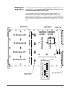
Step 2. Determine M-Module Layout
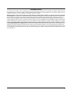
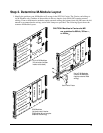
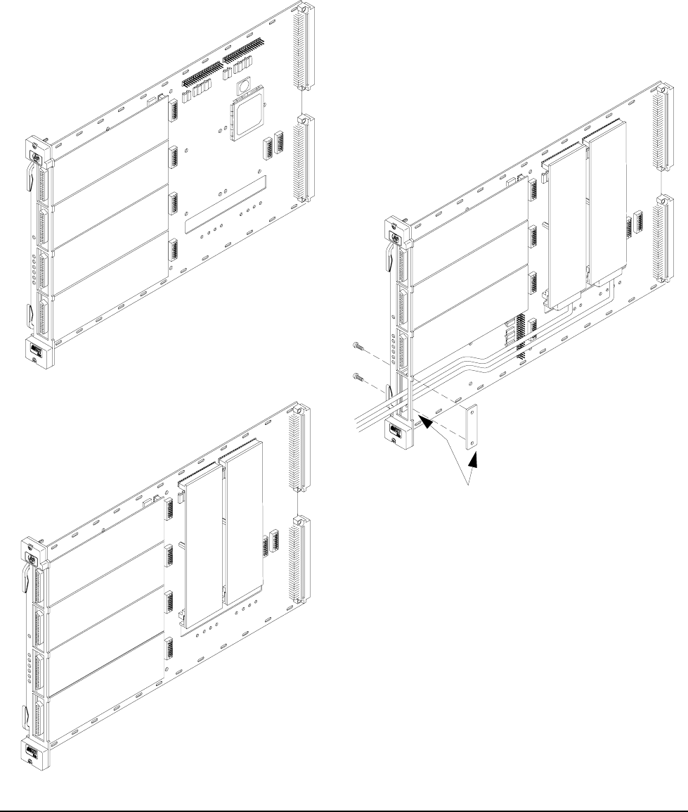
1. Identify the positions your M-Modules will occupy in the E2251A Carrier. The Carrier can hold up to
six M-Modules only if neither of the modules in the two interior slots (M4 & M5) require external
cabling. If one or both interior modules require external cabling, the bottom-front slot (M0) must be left
unused to accommodate the wiring; strain relief clamps are provided. The following figure shows the
common M-Module layouts.
Up to 4 M-Modules
in front slots (neither
interior slot used)
Up to 5 M-Modules
(interior M-Modules
require external field
wiring)
6 M-Modules
(all slots used, interior
M-Modules do not require
external field wiring)
M
-
M
o
d
u
l
e
M
0
M
-
M
o
d
u
l
e
M
1
M
-
M
o
d
u
l
e
M
2
M
-
M
o
d
u
l
e
M
3
M
-
M
o
d
u
l
e
M
3
M
-
M
o
d
u
l
e
M
3
M
-
M
o
d
u
l
e
M
2
M
-
M
o
d
u
l
e
M
2
M
-
M
o
d
u
l
e
M
1
M
-
M
o
d
u
l
e
M
1
M
-
M
o
d
u
l
e
M
0
M-Module M4
M-Module M5
M-Module M4
M-Module M5
CAUTION: Modules in Carrier slot M5
are restricted to 60Vdc, 30Vac
rms
,
or 42Vac
pk
.
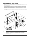
Strain Relief Plates