12
Step 3. Set the Logical Address for each M-Module
Each VXI module or M-Module in a VXI system must have a unique logical
address. The logical address is used by the VXI resource manager to identify
instruments. When the logical address of a module is set to a direct multiple
of 8 (such as 8, 16, 24, ... 256), that module is considered an “instrument”.
An instrument's secondary address (used to program the module from GPIB)
is derived by dividing the instrument logical address by 8. For example, a
logical address of 24 is a secondary address of 03.
Guidelines for
Determining Logical
Addresses
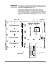
The E2251A comes from the factory with the M-Module logical address
switches set to 0.
1
In the E2251A M-Module Carrier, logical address 0
instructs the Carrier to ignore that slot and the Carrier does not report it to
the VXI system resource manager.
You must
set the logical address switches for each M-Module installed
in the E2251A Carrier.
If you are using an E1406 Command Module set M-Module addresses to a
multiple of 8 (i.e., 8, 16, 24, 32, . . . 256). Do not set any M-Module logical
address to the same value as any other M-Module or any other VXI module
in the system. You can use up to 31 M-Modules (up to seven Carriers) with
an E1406 Command Module or 255 M-Modules (up to 51 Carriers) with
embedded controllers, VXLink, or MXIbus controllers.
Note Multiple-module Scanning Voltmeter or Switchbox instruments are not
supported with M-Modules on the E2251A Carrier. Multiple-module
instruments can only be created using standard B- or C-size VXI modules.
Unused Slots on the
Carrier
Unused slots on the E2251A Carrier should have their logical address set to
0 (zero). With the logical address set to 0, the Carrier disables the circuits
(interrupt, reserved memory, etc.) for that slot.
1. Note that in a standard VXI system, logical address 0 is reserved for the VXIbus command module / resource
manager. On the E2251A Carrier however, logical address 0 causes the Carrier to disregard that M-Module
slot.


