


33
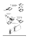
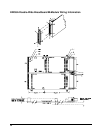
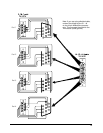
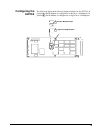
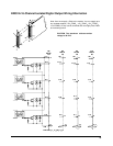
E2274A 4-Channel Power Relay Wiring Information
Caution All three connector pins for each relay contact must be
connected together in the field wiring for maximum current
capability. For example, for Channel 1, pins 1, 16, and 31 (for
NC contacts) must be wired together in the field wiring, likewise
pins 3, 18, and 33 (for the NO contact) and pins 2, 17, and 32 (for
channel common). You may need to run separate wires from
each connector pin and unite them at the device under test or in
your cable.
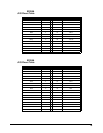
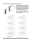
NC = N ormally Close d
NO = Normally Open
com = Common
No Connection: Pins 7, 19, 26
CGND:Pins14,15,30,37,44
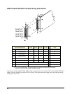
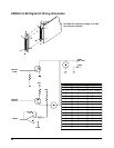
MAXIMUM VOLTAGE/CURRENT: The maximum voltage
that may be applied to any connector on the E2274A is
125 VDC, 141 VAC rms, or 200 VAC peak. These limits
apply only if the product is installed in a humidity-con-
trolled (<60% RH) environment where airborne contami-
nants and transients are controlled, and there is NOT a
relay connection made to power mains. If these condi-
tions CANNOT be maintained, then the maximum volt-
age is 60 VDC, 48 VAC rms or 68 VAC peak.
The maximum current (non-inductive) that may be
applied to the E2274A is 5 ADC, 5 AACpeak per switch.
Maximum power is 100W DC, 100VA AC, per switch;
300WDC, 300VA AC per M-module.