


DX-700 • User’s Guide • Rev 02 207
aK==cáÄÉêäáåâ=kkf=fåëí~ää~íáçå
Overview
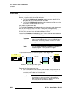
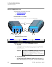
• Electronically, the Fiberlink NNI Receiver and Transmitter modules are nearly
identical. Each module receives data at one end, and transmits it at the other end.
The main difference is in how the modules are powered.
~ The Fiberlink NNI Transmitter receives DC power from the DX-700
processor via the NNI cable.
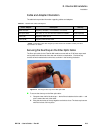
~ The Fiberlink NNI Receiver has an AC line cord for 120/240VAC input.
Internally, the receiver includes a power supply to power the unit and
provide startup power for the LED tiles.
• With the exception of Status LEDs on the modules, there are no methods by
which the user can communicate with the modules. Each module acts simply as a
translator between NNI and fiber optic signaling.
• On their own, the Fiberlink NNI modules do not generate any form of video test
patterns. To generate a test pattern through a
Transmitter and Receiver pair, you
must be using Barco “legacy” tiles and the DX-700
Display Management Menu.
For more information, refer to the “
Managing Fiberlink Settings” section on
page 130 of Chapter 4.
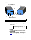
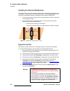
• Each module includes sealed LED indicators to show the current state of the link.
Refer to the “
Fiberlink NNI Hardware” section on page 208 for details.
Note
IP stands for Ingress Protection, as defined by the
International Electrotechnical Commission. The IP-65
standard represents a dust-tight seal that also protects
against ingress from low-pressure water jets against the
enclosure. It does not protect against immersion in water.
Note
For safety, the 120/240VAC power supply inside the Fiberlink
NNI
Receiver is enclosed with a sealed and strain relieved
captive power cord.