


DX-700 • User’s Guide • Rev 02 47
2. Hardware Orientation
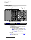
DX-700 Rear Panel
asf=lìíéìí=jçÇìäÉ
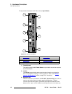
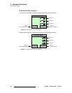
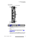
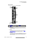
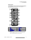
The figure below illustrates the DX-700’s DVI Output Module.
Figure 2-8. DX-700 DVI Output Module
1) Thumb Screws
Two captive, spring-loaded Thumb Screws are provided to secure the module
into the DX-700 chassis.
2) Latches
Two Latches are provided to ensure precise module insertion and extraction.
Care is required when inserting or removing modules. Refer to the “
Module
Insertion and Extraction” section on page 57 for instructions.
3) DVI Outputs
Three DVI-I connectors are provided for DVI Outputs, which connect to existing
(legacy) LED products such as MiPIX and OLite 612. Each output can drive one
attached display from any portion of a selected source image. Each output is
1) Thumb Screws 3) DVI Outputs
2) Latches
LED OUT 1 LED OUT 2 LED OUT 3
2
2
3
1
1