


42 DX-700 • User’s Guide • Rev 02
2. Hardware Orientation
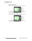
DX-700 Rear Panel
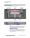
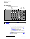
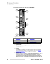
The figure below illustrates the DX-700’s universal Input Module.
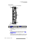
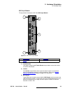
Figure 2-3. DX-700 Input Module
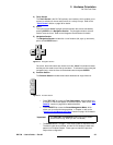
1) Thumb Screws
Two captive, spring-loaded Thumb Screws are provided to secure the module to
the DX-700 chassis.
2) Latches
Two Latches are provided to ensure precise module insertion and extraction.
Care is required when inserting or removing modules. Refer to the “
Module
Insertion and Extraction” section on page 57 for instructions.
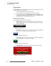
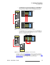
3) Expansion Out
One DVI-I connector is provided for the EXP OUT (Expansion Out) port, which is
used only with external and cross-bank stacking configurations. The port
connects input modules together, guaranteeing that inputs are identical across
banks or units. Input 1 on the “master” must connect to input 1 on the slave, etc.
1) Thumb Screws 5) HD / SDI Input
2) Latches 6) Component Input
3) Expansion Out 7) DVI / Expansion Input
4) RGBHV Input
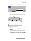
EXP OUT DVI / EXP IN
RGBHV
1 - HD/SDI - 2
Y / COMP C / Pb Pr
2
2
6
4
3
5
7
1
1