


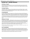
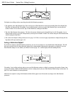
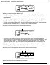
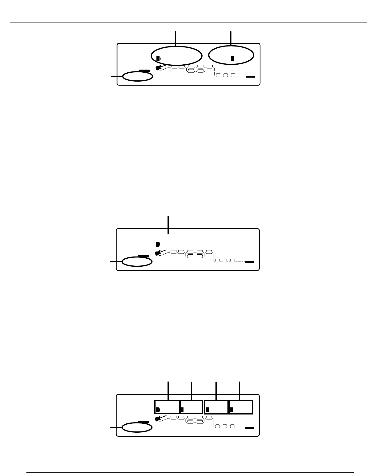
The Display is now telling you three things about the Noise Gate
1. This is showing that the type of effect you are about to edit is the Noise Gate, and that the effect is on. The number 1 icon before the word
“on” indicates that in order to access the on/off parameter, you must press the number 1 button. The status can then be changed by
rotating the Data Wheel.
2. This is the default setting for the Noise Gate. The Noise Gate default shown here is factory default 1 (F1)which is a Low Threshold setting.
The number 4 icon which precedes the F1 value, indicates that in order to access the default parameter, you must press the number 4
button. The default can then be changed by rotating the Data Wheel. See page 22 for a complete list of defaults.
3. The bottom corner of the display is showing that there are 3 pages of parameters associated with the Noise Gate, and that you are on the
first of these three pages. The Next Page button can be used to access page 2 of the Noise Gate parameters.
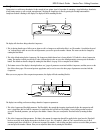
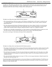
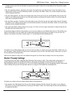
Once you have accessed page 2 of the Noise Gate, the display will look something like this:
1. This is the type of Noise Gate that you are going to use. You have two choices of Noise Gate types. The different types are basically
changing the plascement of the Gate in the signal path. Silencer 1 puts the Noise Gate detector at the input of the RP21D before the signal
enters the Preamp. Silencer 2 places the gate detector at the end of the Preamp after the Preamp modules. Silencer 2 is also more
sensitive to the signal that is present, and not as likely to shut while you are playing. Press the number one button and rotate the Data
Wheel to change the type of Gate.
2. This section of the display is showing that there are 3 pages of parameters associated with the Noise Gate, and that you are on the second
of these three pages. The Next Page button can be used to access page 3 of the Noise Gate parameters.
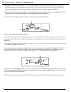
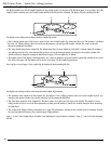
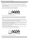
After you have accessed the third page of the Noise Gate parameters, the display will look something like this:
The display it now telling you five more things about the Noise Gate parameters.
4
FACTORY USER
%kHz
msdB
-60
1
CHANGEDLINK
%kHz
msdB
4
2
CHANGEDLINK
%kHz
msdB
1
LINK
%kHz
msdB
4
LINK
PAGE OF
3
COMP WAH TUBE EQ
L/R OUTS
DIGITAL
CLIP
#
b
GATE
SEAMLESS
BANK
EQDIST
12
5
ThreshAtten AttackRelse
3
3
3
4
3
4
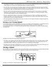
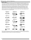
FACTORY USER
%kHz
msdB
2
1
CHANGEDLINK
%kHz
msdB
4
2
CHANGEDLINK
%kHz
msdB
S 1to
LINK
%kHz
msdB
4
LINK
PAGE OF
3
COMP WAH TUBE EQ
L/R OUTS
DIGITAL
CLIP
#
b
GATE
SEAMLESS
BANK
EQDIST
1
2
Type:Silencer2 Post T&D
3
3
2
4
FACTORY USER
%kHz
msdB
On
1
CHANGEDLINK
%kHz
msdB
2
CHANGEDLINK
%kHz
msdB
LINK
%kHz
msdB
4
LINK
PAGE
1
OF
3
COMP WAH TUBE EQ
L/R OUTS
DIGITAL
CLIP
#
b
GATE
SEAMLESS
BANK
EQDIST
12
3
Noise Gate LoThresh
F 1
18
RP21D User’s Guide Section Two - Editing Functions