33
MR-8HD/CD Owner’s Manual (Basic operations)
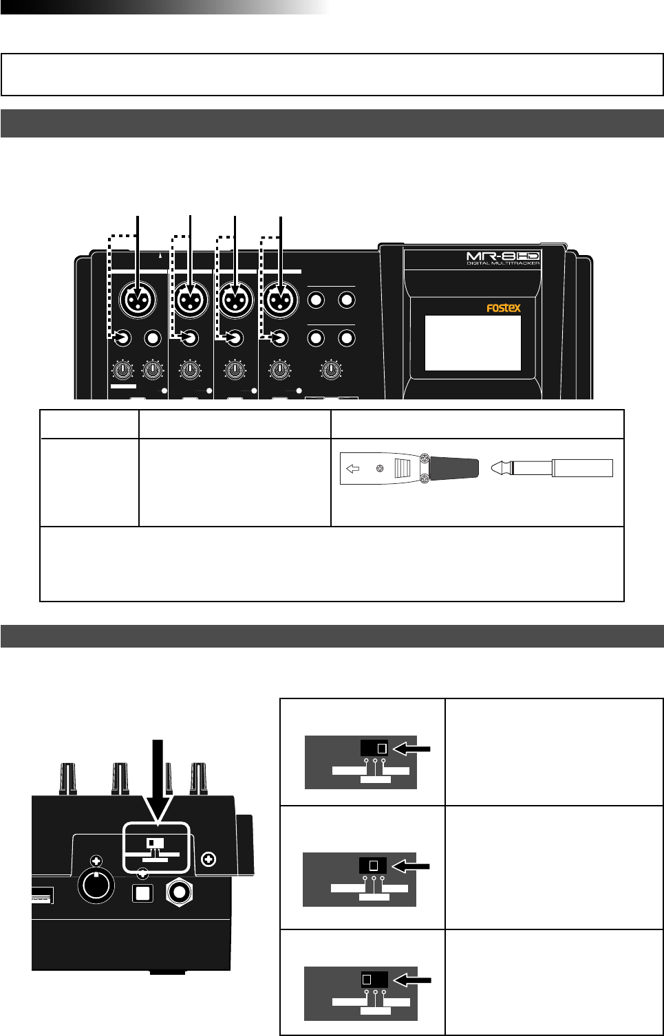
The MR-8HD/CD provides four input channels: [INPUT A], [INPUT B], [INPUT C] and [INPUT D].
Each channel provides both the XLR and 1/4" phone connectors.
INPUT A
INPUT B INPUT C INPUT D
INPUT A
INPUT B
INPUT C
INPUT D
• When you use the [INPUT A] channel, set the [INPUT A SELECT] switch on the rear panel
appropriately.
• If you use a condenser microphone, use the XLR (balanced) connector. The MR-8HD/CD can
supply the phantom power (see page 128).
Available input connectors
Shapes of connectable connector
Input channel
Either of the XLR (balanced) con-
nector or phone (unbalanced) jack
can be used (if both connectors
are plugged, the phone jack is ef-
fective).
Input channel
When you use the [INPUT A] channel, you must set the [INPUT A SELECT] switch on the rear panel
appropriately.
[INPUT A SELECT] switch
INPUT A SEL
MIC/LINE
GTR CLEAN
GTR DIST
INPUT A SEL
MIC/LINE
GTR CLEAN
GTR DIST
INPUT A SEL
MIC/LINE
GTR CLEAN
GTR DIST
“MIC/LINE” position
“GTR DIST” position
“GTR CLEAN” position
Both the [BAL] XLR and [UNBAL/GUI-
TAR] phone connectors can be used.
Set the switch to this position when the
source is an external microphone or
line level source.
Both the [BAL] XLR and [UNBAL/GUI-
TAR] phone connectors can be used.
You can adjust the input level and dis-
tortion using the [TRIM] and [DISTOR-
TION] controls respectively. You can
also use the amp simulation insert ef-
fect.
Both the [BAL] XLR and [UNBAL/GUI-
TAR] phone connectors can be used.
You can adjust the input level using the
[TRIM] control. You can also use the
amp simulation insert effect.
XLR-3-12C type
PHONE plug
MIN
MAX
LINE MIC LINE MIC LINE MIC LINE MIC
PHONES VOL
L
STEREO OUT
R
2
PHONES
1
MAXMIN
BAL
BALBAL
TRIM
UNBAL
PEAK
TRIM
UNBAL
PEAK
TRIM
UNBAL
PEAK
PEAK
DISTORTION
GUITAR
/GUITAR
INPUT A SELECT
INSERT
BAL
UNBAL
TRIM
INPUT A
INPUT B INPUT C INPUT D
INPUT A SEL
B
HOST
DIGITAL
OUT FOOT SWMIDI OUT
GTR CLEAN
MIC/LINE
GTR DIST
[INPUT A SELECT] switch
Input connection


