11
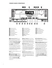
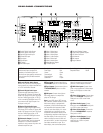
C Video 2 Video Input: Connect this
jack to the
PLAY/OUT composite video
jack on a second VCR or other video
source.
D Video 2 Audio Inputs: Connect
these jacks to the
PLAY/OUT audio jacks
on a VCR or other video source.
E Video Monitor Outputs: Connect
these jacks to the composite and/or S-
Video input of a TV monitor or video pro-
jector to view the output of any video
source selected by the receiver’s video
switcher.
If you would like to make an S-Video
recording from the source connected to
the
DVD S-Video Input 7, you may use
the
Video Monitor Output E S-Video
jack when connected to a compatible
recording device. However, you will not be
able to monitor the video signal from your
video display.
F TV Audio Inputs: Connect these
jacks to the Audio Out jacks on a TV or
other video source.
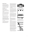
G Surround Speaker Outputs:
Connect these outputs to the matching +
or – terminals on your left and right sur-
round speakers. When making speaker
connections always make certain to
maintain correct polarity by connecting
the colored (+) terminals on the AVR480
(see chart above) to the red (+) terminals
on the speakers and the black (–) termi-
nals on the AVR480 to the black (–) termi-
nals on the speakers. (See page 15 for
more information on speaker polarity.)
H Front/Center Speaker Outputs:
Connect these outputs to the matching +
or – terminals on your front/center speak-
ers. When making speaker connections,
always make certain to maintain correct
polarity by connecting the colored (+) ter-
minals on the AVR480 (see chart above)
to the red (+) terminals on the speaker
and the black (–) terminals on the
AVR480 to the black (–) terminals on
the speakers. (See page 15 for more
information on speaker polarity.)
I AC Power Cord Jack: Connect the
AC power cord to this jack when the
installation is complete. To ensure safe
operation, use only the power cord sup-
plied with the unit. If a replacement is
required it must be of the same type and
capacity.
Depending on the electrical requirements
in your area or the wiring in your home,
the power cords included with your AVR
may not be the correct ones, and you may
need to contact your local JBL distributor
to obtain the correct power cord.
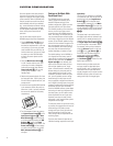
J AM Antenna: Connect the AM loop
antenna supplied with the receiver to these
terminals. If an external AM antenna is
used, make connections to the
AM and
GND terminals in accordance with the
instructions supplied with the antenna.
K FM Antenna: Connect the supplied
indoor or an optional external FM antenna
to this terminal.
L Region Selector: Select the position
corresponding to the country in which the
AVR will be used (C, S or K) so that the
video standard and the FM tuner’s fre-
quency increments will be correct. (See
page 31 for more information on setting
the
Region Selector L.)
IMPORTANT NOTE: Any adjustments
made to the
Region Selector L will
not take effect unless the unit is first
fully turned off by pressing the
Main
Power Switch
1 until it pops out
and the word “OFF” appears on the top
of the button.


