


15
INSTALLATION AND CONNECTIONS
After unpacking the unit, and placing it on
a solid surface capable of supporting its
weight, you will need to make the connec-
tions to your audio and video equipment.
Audio Equipment Connections
We recommend that you use high-quality
interconnect cables when making connec-
tions to source equipment and recorders
to preserve the integrity of the signals.
When making connections to audio
source equipment or speakers it is always
a good practice to unplug the unit from
the AC wall outlet. This prevents any pos-
sibility of accidentally sending audio or
transient signals to the speakers that may
damage them.
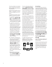
IMPORTANT NOTE: In order to clearly
identify all connectors and simplify
installation, as per the new EIA/CEA-863
standard, all connections are color-coded
as follows:
For speakers and audio in/outputs: white
(left, speakers front) and red (right,
speakers front)
For speakers: green (center), blue (left
surround) and gray (right surround)
For audio output: purple (subwoofer)
For composite video in/outputs: yellow
For coaxial digital audio in/outputs:
orange
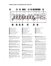
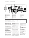
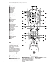
1. Connect the analog output of a CD
player to the
CD Inputs
6
.
NOTE: When the CD player has both
fixed and variable audio outputs it is best
to use the fixed output unless you find
that the input to the receiver is so low
that the sound is noisy, or so high that
the signal is distorted.
2. Connect the analog Play/Out jacks of a
cassette deck, MD, CD-R or other audio
recorder to the
Tape Input Jacks
4
.
Connect the analog Record/In jacks on
the recorder to the
Tape Output
Jacks
5
on the AVR480.
3. Connect the digital output of any
digital device to the appropriate input
connections on the AVR480 rear
panel. Note that the
Optical and
Coaxial Digital Inputs
12
may
be used with a Dolby Digital or DTS
source or the output of a conventional
CD, MD or LD player’s PCM (S/P-DIF)
output.
4. Connect the
Coaxial Digital Output
0
on the rear panel of the AVR to the
matching digital input connection on a
CD-R or MiniDisc recorder.
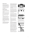
5. Assemble the AM Loop Antenna supplied
with the unit so that the tabs at the bottom
of the antenna loop snap into the holes in
the base. Connect it to the
AM and GND
Screw Terminals
a .
6. Connect the supplied FM antenna to
the
FM (75-ohm) Connection K. The
FM antenna may be an external roof
antenna, an inside powered or wire
lead antenna or a connection from a
cable system. Note that if the antenna
or connection uses 300-ohm twin-lead
cable, you must use a 300-ohm-to-75-
ohm adapter to make the connection.
Select the position corresponding to
the country in which the AVR will be
used (China, Singapore or Korea) so
that the FM tuner’s frequency incre-
ments will be correct. If the AVR will
be used in a country other than one of
those listed, contact your JBL dealer
for information on which position
should be used. (See page 31.)
7. Connect the front, center and surround
Speaker Outputs
GH
to the
respective speakers.
To ensure that all the audio signals are
carried to your speakers without loss of
clarity or resolution, we suggest that you
use high-quality speaker cable. Many
brands of cable are available and the
choice of cable may be influenced by the
distance between your speakers and the
receiver, the type of speakers you use,
personal preferences and other factors.
Your dealer or installer is a valuable
resource to consult in selecting the
proper cable.
Regardless of the brand of cable selected,
we recommend that you use a cable con-
structed of fine, multistrand copper with
an area greater than 2mm
2
(14-gauge or
smaller; when specifying cable size in
terms of gauge, remember that the lower
the number, the thicker the cable).
Cable with an area of 1.5mm
2
(16-gauge)
may be used for short runs of less than
4m (10 feet). We do not recommend that
you use cables with an area less than
1mm
2
(18-gauge) due to the power loss
and degradation in performance that
will occur.
Cables that are run inside walls should
have the appropriate markings to indicate
listing with UL, CSA or other appropriate
testing agency standards. Questions
about running cables inside walls should
be referred to your installer or a licensed
electrical contractor who is familiar with
the applicable local building codes in
your area.
When connecting wires to the speakers,
be certain to observe proper polarity.
Remember to connect the “negative” or
“black” wire to the same terminal on both
the receiver and the speaker. Similarly,
the “positive” or “red” wire should be
connected to the corresponding colored
terminals on the AVR480 and speaker.
NOTE: While most speaker manufactur-
ers adhere to an industry convention of
using black terminals for negative and red
ones for positive, some manufacturers
may vary from this configuration. To
ensure proper phase and optimal perform-
ance, consult the identification plate on
your speaker or the speaker’s manual to
verify polarity. If you do not know the
polarity of your speaker, ask your dealer
for advice before proceeding, or consult
the speaker’s manufacturer.