


4
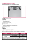
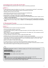
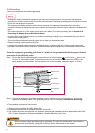
The following circuit symbols are used to describe the AC module circuit in this manual.
1-4 Circuit Symbols
/ PV module: Equipment that receives solar energy and generates DC power.
/ Inverter: Equipment that converts DC power into AC power.
/ Utility-Interactive inverter: Inverter connected in parallel with the grid to supply power.
/ Micro inverter: Inverter designed with minimal size to supply power to each PV module.
DC (Direct Current) supply. Generated from PV module.
AC (Alternating Current) supply. Generated from utility and micro inverter. Used in
electric appliances.
Represents the phase of AC. The number in front of this symbol represents the
number of phases.
Terminal for EGC (Equipment Grounding Conductor) normally used to connect non–
current carrying metal parts of equipment together.
Terminal for GEC (Grounding Electrode Conductor) connecting EGCs and neutral
conductors to the ground for grounding.
Circuit breaker switch. l : ON, O : OFF.
Circuit Symbol Description
1-3 FCC Guidelines
You are cautioned that changes or modifications to this unit not expressly approved by the party responsible for
compliance could void the user’s authority to operate this equipment.
This equipment has been tested and found to comply with the limits for a Class B Digital Device, pursuant to Part
15 of the FCC Rules. These limits are designed Part 15 of the FCC Rules. These limits are designed to provide
reasonable protection against harmful interference in a residential installation. This equipment generates, uses and
can radiate radio frequency energy and, if not installed and used in accordance with the instruction, may cause
harmful interference to radio communication. However, there is no guarantee that interference will not occur in a
particular installation. If this equipment does cause harmful interference to radio or television reception, which can
be determined by turning the equipment off and on, the user is encouraged to try to correct the interference by one
or more of the following measures:
- Reorient or relocate the receiving antenna.
- Increase the separation between the equipment and receiver.
- Connect the equipment into an outlet on a circuit different from that to which the receiver is connected.
- Consult the dealer or an experienced radio/TV technician for help.
This device complies with part 15 of the FCC rules. Operation is subject to the following two conditions:(1) This
device may not cause harmful interference, and (2) This device must accept any interference received, including
interference that may cause undesired operation.
Indoor use only
FCC Caution: For indoor use only; outdoor use or in any other environments not covered in this manual may
violate the FCC regulation and void the user’s authority to use the product.
Specially, within the 5.15-5.25 GHz band, U-NII device is restricted to indoor operations to reduce any potential for
harmful interference to co-channel MSS operations.
FCC RF Radiation Exposure Statement:
This equipment complies with FCC radiation exposure limits set forth for an uncontrolled environment.
This equipment should be installed and operated with a minimum distance of 8.87 inches (20 cm) between the
radiator and your body. End users must follow the specific operating instructions for satisfying RF exposure
compliance. This transmitter must not be co-located or operating in conjunction with any other antenna or
transmitter.
CAUTION: Regulations of the FCC and FAA prohibit airborne operation of radio-frequency wireless devices
because their signals could interfere with critical aircraft instruments.
For Micro inverter & Communication Gateway
For Communication Gateway