


117
BCM 104
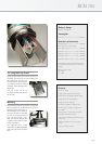
Delivery Range
BCM104 Microphone
Catalog No.
BCM 104................................................... ni.........008483
Selection of Accessories
Power supply, N248 EU...............blk ...... 008537
Power supply, N248 US................blk ...... 008538
Power supply, N248 UK............... blk ...... 008539
Headgrille, BCK...................................... ni ......... 008520
(incl. Assortment of colored rings)
Swivel Mount, SG5............................................. 008529
Popscreen, PS15.................................. blk ...... 008472
Popscreen, PS20a............................. blk ...... 008488
Windscreen, WS47............................ blk ...... 006826
Microphone cable, IC3mt............. blk ...... 006543
A complete survey and detailed descriptions of all
accessories are contained in the accessories
catalog
Meaning of color codes:
blk = black,
ni = nickel
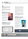
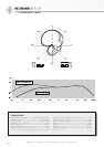
Electrical features
Instead of a transformer to couple the microphone
output to the supply voltage, the BCM104 has
an electronic circuit which, like a transformer,
provides for good com-
mon mode rejection.
Interference induced
in the balanced modu-
lation line is thus sup-
pressed effectively.
With a very low self-
noise of 7dB(A), and
an overload capability
extending to 138dB
SPL, the BCM 104 has
a dynamic range of
131dB (A-weighted).
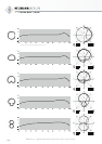
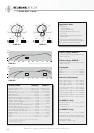
Filter and Preattenuation
The BCM104 amplifier has a linear operation
down to 20Hz. An active filter efficiently sup-
presses signals below this frequency. In order to
compensate for the proximity effect, an electronic
high-pass filter, activated by a switch, is built into
the microphone. This filter reduces frequencies
below 100 Hz by 12dB/octave.
A 14-dB preattenuation switch is provided in or-
der to adjust the sensitivity, if necessary, to circuits
designed for dynamic microphones. This will in-
crease the self noise level accordingly.
Both switches are located inside the microphone
housing, since they will normally be operated only
once, when the broadcasting facility is set up.
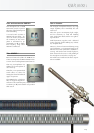
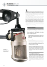
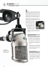
Mounting
The preferred mode of operation is to suspend
the microphones in the Broadcast Line from a stan-
dard studio boom arm. A thread adapter to fit dif-
ferent connector threads is included. In order to
provide protection from structure-borne noise,
both the capsule and the microphone in its mount
are elastically suspended.
The optional SG 5 swivel mount allows addition-
al angling of the microphone by ±90 degrees.
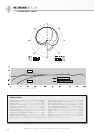
Features
•Large-diaphragm condenser capsule
•Cardioid directional characteristic
•Characteristic, functionally optimized design
•Integrated, neutral pop protection
•Integrated elastic suspension
•Individual headgrilles for different users
•Colored rings to identify the replacement
headgrilles
•Easy removal and cleaning of microphone
headgrille (with bayonet mount)
•Mechanical compatibility with standard studio
boom arms
•Internal switches: high-pass and pre-
attenuation