


59
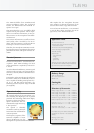
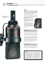
TLM 170 R
Technical Data
Acoustical operating principle.........................Pressure gradient transducer
Directional pattern............................... Omnidirectional, wide angle cardioid,
cardioid, hypercardioid, figure-8
Frequency range...................................................................................20 Hz...20kHz
Sensitivity at 1 kHz into 1 kohm................................................................8 mV/Pa
Rated impedance..................................................................................................50 ohms
Rated load impedance...............................................................................1000ohms
Signal-to-noise ratio, CCIR
1)
(rel. 94dB SPL)...........................................68 dB
Signal-to-noise ratio, A-weighted
1)
(rel. 94dB SPL)............................80 dB
Equivalent noise level, CCIR
1)
.............................................................................. 26 dB
Equivalent noise level, A-weighted
1)
..........................................................14 dB-A
Maximum SPL for THD 0.5%
2)
....................................................................144 dB
Maximum SPL for THD 0.5% with preattenuation
2)
..................... 154 dB
Maximum output voltage...................................................................................10 dBu
Dynamic range of the microphone amplifier (A-weighted)........130 dB
Supply voltage (P48, IEC61938)......................................................48V ± 4V
Current consumption (P48, IEC61938)......................................................3 mA
Matching connector.................................................................................................XLR3F
Weight ...............................................................................................................................625 g
Diameter........................................................................................................................60 mm
Length.......................................................................................................................... 152 mm
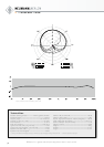
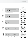
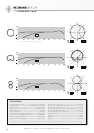
very smooth frequency response for all polar
patterns over a wide acceptance angle. The
curves are flat and parallel to the 0° frequency
curve up to 10 kHz within an
angle of ± 100°.
As a result the TLM170 R
has a very even diffuse-field
response for all polar patterns.
This is important in a rever-
berant environment, as more
reflections arrive at the micro-
phone from different direc-
tions. The acoustic informa-
tion is not affected in its tonal
quality when recorded by the
microphone. This characteris-
tic is achieved without re-
sorting to corrective resonance effects.
Therefore, the microphone maintains an excel-
lent impulse response reproducing all transient
phenomena of music and speech without any
coloration.
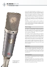
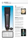
The capsule is elastically mounted to avoid any
structure borne noise that could interfere with
its operation.
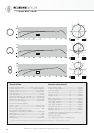
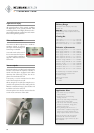
Polar patterns
In addition to the usual directional polar
patterns: omnidirectional, cardioid, and
figure-8, we have added a hypercardio-
id and wide-an-gle cardioid character-
istic. When compared to the standard
cardioid pattern, the hypercardioid
characteristic suppresses sound from
the side more efficiently. The wide-
angle polar pattern is especially useful
to record large sound sources.
1)
according to IEC 60268-1; CCIR-weighting acccording to CCIR 468-3, quasi peak; A-weighting according to IEC 61672-1, RMS
2)
measured as equivalent el. input signal
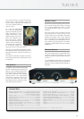
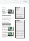
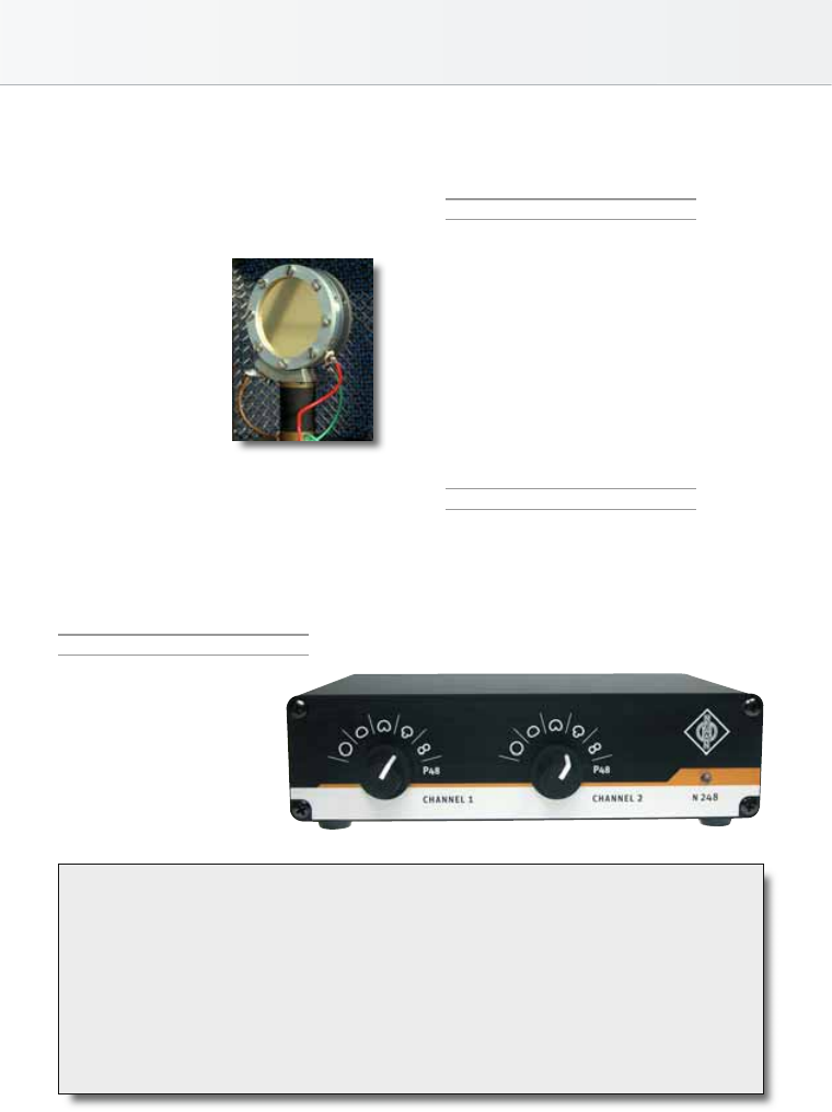
Remote control
The N248 controls the polar pattern remote-
ly by varying the phantom voltage. The range
is ±3 V of the nominal 48V value. (Accord-
ing to DIN standard a range of ±4 V is per-
missible.)
The rotary switch on the microphone must be
in the position R (= remote control). In this
switch position the TLM170 R microphone
analyses the absolute value of the phantom
power and selects the corresponding polar pat-
tern. A standard 3-pin microphone cable is
used, similar to the microphone’s convention-
al operation. Cable lengths may be up to 300 m
(1000feet).
Electrical features
The letters TLM stand for “transformerless mi-
crophone”. With TLM technology the usual
output transformer is replaced by an electron-
ic circuit.
As with traditional transformers, it ensures good
common mode rejection, and prevents RF in-
terference, that may influence the balanced au-
dio signal.