


91
MIDI Implementation
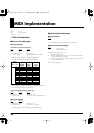
3. Exclusive Communication
■
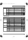
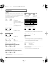
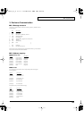
3.1 Message structure
All exclusive communications are based on following structure ( Roland Exclusive
Format Type IV ).
Byte
Description
a F0H Exclusive status
b 41H Roland ID #
c dev Device-ID # = MIDI basic channel -1
d 14H Model-ID # (D-50)
e xxH Command-ID #
[f aaH Address MSB ] [ ] depend on Command-ID
[g bbH Address ]
[h ccH Address LSB ]
[i ddH Data ]
[: ]
j sum Checksum
k F7H EOX (End Of Exclusive)
Summed value of the all bytes between Command-ID and EOX (f-j) must be 00H (7
bits). It doesn’t include Command-ID and EOX.
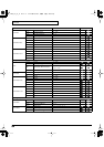
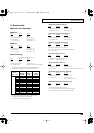
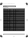
■
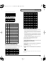
3.2 Address mapping
●
Temporary area
Address
Description
[00-00-00] Upper Partial-1 temp-area
[00-00-40] Upper Partial-2 temp-area
[00-01-00] Upper Common temp-area
[00-01-40] Lower Partial-1 temp-area
[00-02-00] Lower Partial-2 temp-area
[00-02-40] Lower Common temp-area
[00-03-00] Patch temp-area
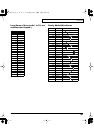
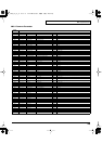
●
Work area
You can transmit/receive data in the currently selected patch bank using the
following address.
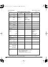
Address
Description
[02-00-00] Patch Memory 1-1
[02-03-40] Patch Memory 1-2
: :
[03-5C-40] Patch Memory 8-8
[03-60-00] Reverb Data 17
[03-62-78] Reverb Data 18
: :
[04-0C-08] Reverb Data 32
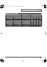
Each patch memory consists of the followings.
Offset Description
[00-00-00] Upper Partial-1
[00-00-40] Upper Partial-2
[00-01-00] Upper Common
[00-01-40] Lower Partial-1
[00-02-00] Lower Partial-2
[00-02-40] Lower Common
[00-03-00] Patch
vc1_for_XT_e1 91 ページ 2005年3月8日 火曜日 午後12時55分