


424 MKIII MIXER
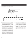
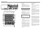
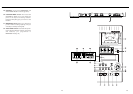
1. POWER switch (on the rear panel): Turns the
424 MKIII on and off.
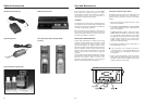
2. Power connector: Connect the power adaptor
for the 424 MKIII to this connector. It is
important that you use only a power adaptor
specially designed for the 424 MKIII which is
designed for use with the voltage in your
area.
3. MIC/LINE INPUTS jacks, Balanced (Channels
1-4): The 3-contact XLR-type connector
accepts balanced microphone signals
ranging from –60 dBV (1 mV) to –20 dBV
(100 mV), depending on the setting of the
TRIM control (#6).
4. MIC/LINE INPUTS jacks, Unbalanced
(Channels 1-4): This 1/4" jack accepts
unbalanced signals ranging from –50 dBV
(3 mV) to –10 dBV (0.3 V), depending on the
setting of the TRIM control (#6).
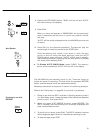
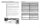
5. SUB INPUT L and R jacks: These jacks are for
cascade connection of an outboard mixer,
etc. The signal input to these jacks is sent to
the MASTER fader. Nominal input level is
–10 dBV (0.3 V).
The SUB IN R jack is also used to accept FSK-
converted MIDI sync signals from devices
such as the optional TASCAM MIDI-Tape
Synchronizer MTS-30.
6. TRIM controls: This is used to set
preamplification level on the MIC/LINE
INPUTS. When TRIM is turned all the way to
the left (LINE position), the preamplifier gain
is low, allowing the jack to accept line level
sources such as electronic instruments. As
you turn TRIM up, the preamplifier gain
increases, and when you turn TRIM full
clockwise (MIC position), the nominal input
sensitivity increases to –50 dBV (3 mV) for
1/4" phone jack, and to –60 dBV (1 mV) for
XLR-type jack.
NOTE
■ DO NOT use both the XLR-type and 1/4"
phone jacks on the same channel at the
same time.
Input Section
39
Features and Controls
40
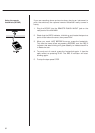
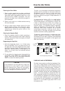
7. INPUT select switches:
(channels 1-4)
This is used to control what the source of the
channel is:
The left position (MIC/LINE) is used when
recording microphones/instruments (in
tracking or overdubbing).
The center position (OFF) is used to shut off
the channel.
The right position (TAPE) is used during
mixdown or bouncing tracks.
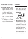
(channels 5 and 6)
This is used to control the source of these
channels. Channel 5 can accept the signals
from equipment connected to odd-numbered
inputs 1, 3 and 5, and channel 6 uses the
even-numbered inputs in the same way. Slide
the switch to the appropriate number to send
the signal from the appropriately-numbered
input to the channel.
Note that if signals are sent through more
than one channel at the same time (e.g.
through channel 1 and 5), the level of these
signals will be doubled. You should allow for
this when mixing.
8. EQ HIGH: This controls the tonality of the
high or "treble" frequencies. Turn it to the
right to boost the signal's high frequency
content emphasizing brilliance or brightness.
Turn it to the left to cut the high frequency
content, if the signal sounds too harsh or
shrill. The EQ shelving point is 10 kHz.
9. EQ MID: The upper knob changes the center
frequency of the MID equalizer from 250 Hz
to 5 kHz. The lower knob controls how much
cut or boost is applied to the band chosen by
the upper knob. Turning the lower knob to
the right amplifies the band up to 12 dB.
Turning it to the left cuts the band down to
–12 dB. At center, there is no effect (flat
response).
10. EQ LOW: Turn the control to the right to
boost bass frequencies and make the sound
relatively heavy. Turn the control to the left to
cut bass and make the sound thinner. The EQ
shelving point is 100 Hz.