117
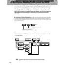
Analog Physical Modeling Synthesis and the AN200
Appendix
■ VCO 1 and VCO 2• • • • • • • • • • • • • • • • • • • • • • • • • • • • • • • • • • • • • • • • • • • •
Here is where the sound begins. The VCO generates a waveform — usually relatively simple ones, such as
sine, saw, and square waves. The AN200 features two independent VCOs, each with an extensive wave set,
providing sound-creating capabilities that are exceptionally complex and flexible — for a dynamic, rich
sound that would be impossible with just one VCO. (Also see Tips 42, 44, and 46.)
What’s more, VCO 1 is actually made up of two oscillators, which can be configured as “master” and “slave.”
Plus, VCO 2 can be used to modulate VCO 1, for even greater sonic complexity.
The PEG block (Tip 36) is used to control how the pitches of the VCOs change over time. LFOs 1 and 2
(Tips 32 - 35) are modulation waves that can be routed not only to the VCO but the VCF and VCA blocks as
well — for creating a variety of special tremolo, wah, and vibrato effects.
■ VCF • • • • • • • • • • • • • • • • • • • • • • • • • • • • • • • • • • • • • • • • • • • • • • • • • • • • •
Here’s where the sound is processed. The VCF takes the sound of the VCOs and filters out certain frequency
ranges. The more complex the sound generated by the VCOs, the greater the sound-shaping potential of
this section.
VCF includes a comprehensive set of different filter types (such as Low Pass, High Pass, Band Pass, and
Band Eliminate), and provides controls for adjusting the Cutoff frequency of the filter, and the Resonance (or
emphasis) of the frequency cutoff point. (Also see Tips 18 - 20.)
The FEG block (Tip 37) is used to control how the filter of the VCF changes over time. A special FEG Depth
control (Tips 20, 38, and 39) also affects VCF operation.
■ VCA • • • • • • • • • • • • • • • • • • • • • • • • • • • • • • • • • • • • • • • • • • • • • • • • • • • • •
Finally, here’s where the sound level is controlled. The VCA (controlled over time by the AEG block; see Tip
36) outputs the sound, before it is sent to the Effect block for more processing. (Also see Tips 15 - 17.)


