


Applying effects 45
—Owner’s Manual
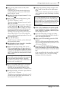
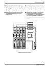
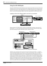
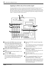
Signal flow through the INSERT I/O jack and the insertion cable
In order to use the INSERT I/O jack to apply an external effect, you will a special insertion
cable as shown in the above diagram. Use the insertion cable to connect the external effect
processor as shown in the following diagram.
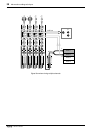
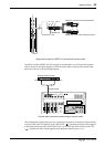
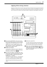
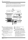
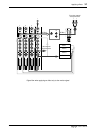
External effect connections when using an insertion cable
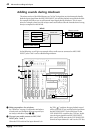
After making these connections, you can record tracks or perform a mixdown in the same way
as usual. When the FLIP switch is in the “MIC/LINE ( )” position, the effect will be applied
to the input signal from MIC/LINE INPUT jack 1 or 2. When the FLIP switch is in the “PB
( )” position, the effect will be applied to the playback sound of track 1 or 2.
HIGH
010
–15 +15
MID
–15 +15
LOW
–15 +15
PAN
LR
AUX
12
10
9
8
7
6
5
4
3
2
1
0
INSERT
I/O
Sleeve Tip
SleeveRingTip
Input jack of the external effect processor
Output jack of the external effect processor
INSERT I/O
jack
5 / 6 7 / 8
2TR IN
CUE MIX TO STEREO
MONITOR SELECT
PITCH
EJECT
ADJUST EDIT UTILITY
CH1
BUS
CH2
REC SELECT
CH3 CH4
LRLR
PEAK HOLD DISPLAY
010010
MULTITRACK MD RECORDER
IN THRUOUT
MIDI
MIC/LINE INPUT
3
21
4 5678
LINE INPUT
AUX SEND
INSERT
I/O
INSERT
I/O
TRACK
DIRECT OUT
STEREO
OUT
2TR IN MONITOR
OUT
12
1234
1
GAIN
CUE
HIGH
LINE
FLIP
MIC/
LINE
MIC
LR
010
–15 +15
PB
P
A
N
L
E
V
E
L
2
GAIN
CUE
HIGH
LINE
FLIP
MIC/
LINE
MIC
LR
010
–15 +15
PB
P
A
N
L
E
V
E
L
3
GAIN
CUE
HIGH
LINE
FLIP
MIC/
LINE
MIC
LR
010
–15 +15
PB
P
A
N
L
E
V
E
L
4
GAIN
CUE
HIGH
LINE
FLIP
MIC/
LINE
MIC
LR
010
–15 +15
PB
P
A
N
L
E
V
E
L
External effect processor
Insertion cable
Output jackInput jack