Installing Optional Hardware
Installing Optional Hardware
Reference 185
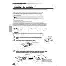
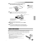
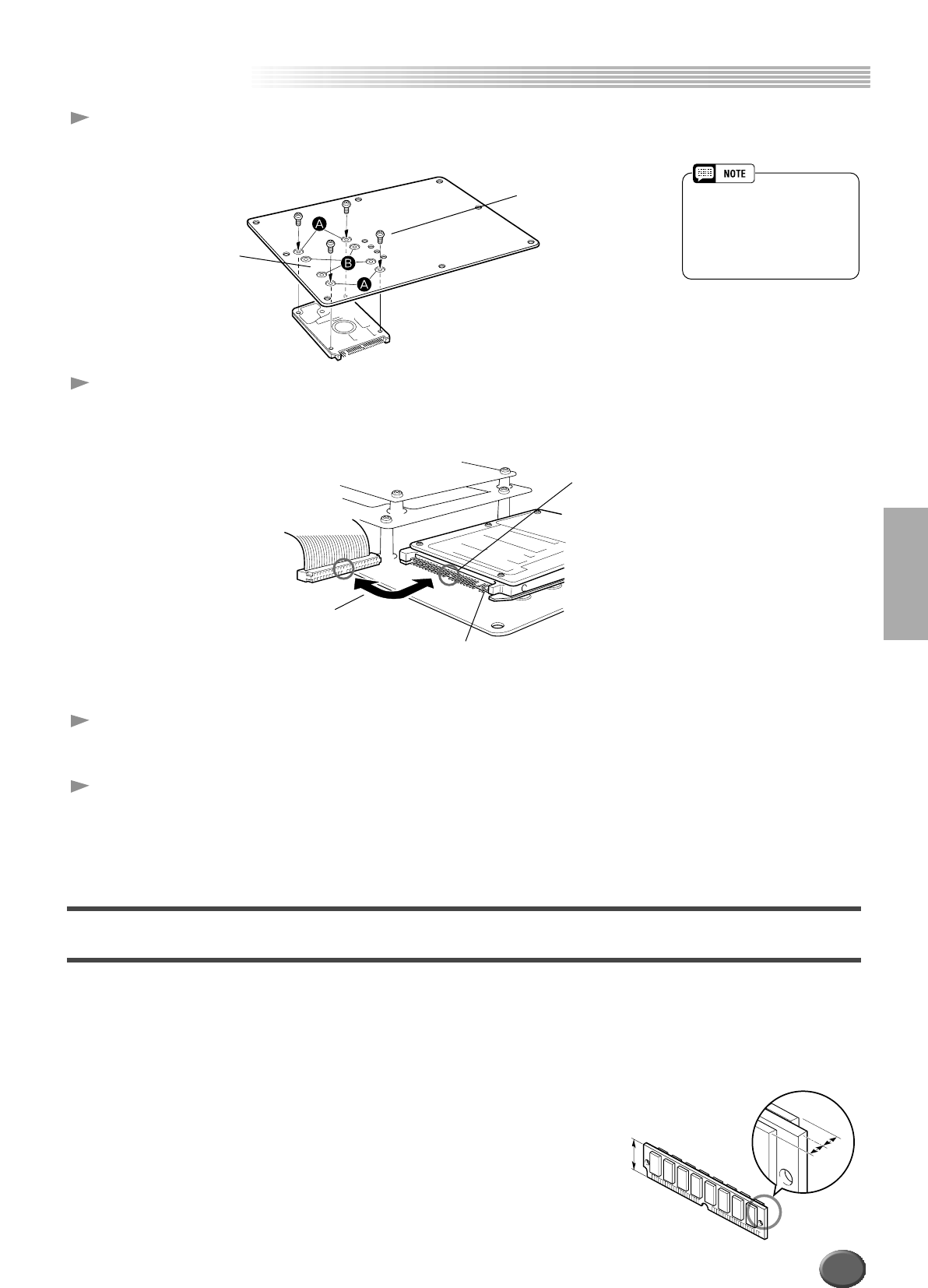
8 Attach the hard disk unit to the Plug-in board/Hard disk
cover using the four screws removed in step 5.
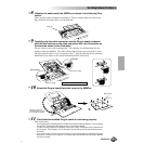
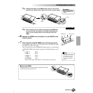
9 Turn the cover over again, and attach the cable connector as
shown.
Undo the cable clip (to the large cable), and plug it into the hard disk socket.
Re-attach the Plug-in Board cable(s) if necessary.
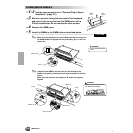
10 Attach the Plug-in board/Hard disk cover to the 9000Pro
(page 183).
11 Check that the installed hard disk is functioning properly.
Turn on the power, go to the DISK display, and execute the Format Hard Disk func-
tion (page 156). If the format is completed with no trouble, the hard disk is OK.
Optional SIMM Installation
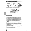
The SIMMs used must meet the following minimum specifications, but this does not guarantee that
they will work properly with the 9000Pro. Make sure to install the SIMMs in pairs only; also make
sure that both modules of the pair are of the same type and memory capacity, and are from the same
manufacturer. Consult with your nearest Yamaha representative or an authorized distributor listed at
the end of this manual before purchasing SIMMs for the 9000Pro.
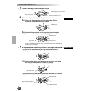
• 16-bit bus compatibility or compliance with JEDEC standards (SIMMs which are only compatible with 32-
bit buses can not be used)
• 70 nanoseconds or faster access time (note: 60 nanosecond SIMMs are faster than 70 nanosecond
SIMMs).
• No more than 18 memory chips on each SIMM module.
• SIMM modules must be no more than 25.4 mm in height and the thickness of the SIMM should not
exceed 8mm on either side when measured from the center of the SIMM. See below.
• SIMMs with parity and EDO DRAM modules can also be used.
• Use only SIMMs of 4-, 8-, 16-, or 32-megabyte capacity.
• Install SIMM memory at your own risk. Yamaha will not be held responsible for any damage or injury
resulting from improper installation.
Silver screws
You should tighten these
two screws first.
• Depending on the type of hard
disk drive you plan to install,
select holes (
A
) or holes (
B
)
to attach the hard disk drive.
* Holes (
A
) are used in this illus-
tration.
Make sure that the pins do not
bend.
In the middle of the hard disk con-
nector is a “missing” pin. Make sure
to align the cable connector (which
has a corresponding “missing” hole)
to the hard disk as shown.
The rightmost 4 pins are unused.
25.4mm
8mm
8mm
183


