


91
Technical Services Group ~ 1-800-283-5936 (USA) ~ 1-801-974-3760
Appendices ~ Appendix C: Control Panel
The Volume Control Panel and Select Control Panel connect to either the Remote
Panel A or B connector of the PSR1212, XAP 800, or XAP 400 and works by
triggering the execution of programmed commands from the XAP/PSR unit. Each
button on the control panel is programmable to execute a single command or a
series of commands. Button function is programmed using G-Ware software (see the
XAP or PSR user manual). Each Control Panel fits inside a standard electrical wall
box and must be installed according to local electrical codes.
Connecting the Control Panel
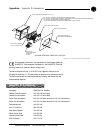
1. Ensure you received a facia plate; a Control Panel assembly with mounting
bracket and two RS-485 Phoenix four-pin connectors; two connector
terminator blocks; a faceplate; two flat HD screws; two pan-head screws;
and an electrical wall box (shown in Figures C.5 and C.6). If any parts are
missing, please contact ClearOne.
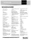
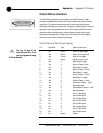
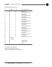
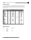
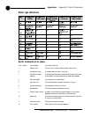
2. Using DIP switches 1–4, assign a unique ID to the Control Panel.
Refer to
Figure C.2 for proper DIP switch settings. If you set an invalid address, all LEDs
on the Control Panel will illuminate.
3. Set DIP switch 8 to the on position if you are using just one Control Panel. If you
have more than one Control Panel daisy-chained to the same Remote Panel
connector, set
only
the
last
Control Panel’s DIP switch 8 to on. Switches 5-7 are
nonfunctional.
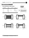
4. Turn off the XAP/PSR unit (unplug the unit).
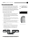
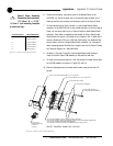
5. Wire each end of a Cat. 5 cable to a connector terminator block. Use one
twisted wire pair for the center - and + connections (pins 2 and 3) and the
other twisted pair for the ground and +15V connections (pins 1 and 4).
Failure to correctly wire the connector can result in damage to the unit.
This equipment must be
installed according to
applicable local electrical
codes.
!
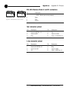
1 2 3 4 5 6 7 8
O N
O N
Figure C.1. DIP switches
Figure C.2. DIP switch settings
Appendix C: Control Panel
Figure C.3. Wiring the Control Panels