


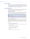
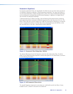
Mix Matrix
The line input process routes incoming signals through a mix matrix to the line outputs.
The mix matrix contains 16 mix-points, one for each input to each output bus with each
mix-point containing a single fader with a range of -24 dB to +12 dB, plus a mute control.
The step resolution is 0.1 dB.
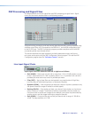
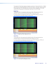
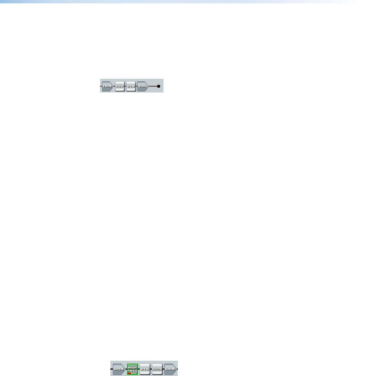
Line Output Chain
Line output chain elements from left to right are as follows:
• Trim (TRIM) — One post-mixer mono gain control per channel with a range of -12 dB
to +6 dB. The step resolution is 0.1 dB.
• Filter (FILT) — Up to nine frequency filters can be inserted in any combination of High
Pass, Low Pass, tone (Bass & Treble shelving), or Parametric Equalizer.
• Dynamics (DYN) — One limiter per block per channel. The limiter prevents clipping
and protects a system against component or speaker damage.
• Volume (VOL) — One output volume control per channel with a range of -100 dB to
0 dB. The step resolution is 0.1 dB. Gain control is provided pre-meter. Mute control is
provided post-meter. A polarity switch (+ or -) is provided.
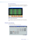
Processor Blocks
Processor blocks are placed in the signal chain to perform specific tasks. There are level
control blocks, signal processor blocks and mix-point matrix blocks (with level control).
Level control processors do not have to be inserted, they are always active. The following
sections provide details of navigation, menus, and other interface operations. The
processor blocks, while performing different functions, have several common elements.
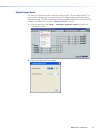
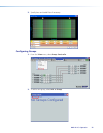
• Insert — All blocks (except level controls) may be inserted by right-clicking on the
desired box and selecting from the context menu or by double-clicking and making a
selection.
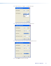
• Remove a process — Active processors can be removed by right-clicking on the box
and selecting Delete or by selecting the block and pressing delete on the keyboard.
This sets the parameters back to default and removes or “deactivates” the block. An
active processor may be replaced by right-clicking and inserting a new processor. A
warning appears to indicate the previous processor is about to be replaced.
• Mute — When a level block (gain, trim or volume) is muted, all signal flow is blocked.
When mute is active a red mark appears in the lower left of the block. Mix-point mute
is indicated by shadowing the mix-point.
• Bypass — When bypass is active, signal flow passes through the block without
processing, regardless of the settings. When bypass is removed, the signal will be
processed according to the parameter settings. A red mark appears in the lower left of
the block (shown below) to indicate it has been inserted, but is currently bypassed.
DMP 44 LC • Operation 15