


SK-96370-144PMC-GDC User Guide
Chapter 3 Jumpers and Switches
© Fujitsu Microelectronics Europe GmbH - 15 - FMEMCU-UG-960014-10
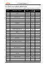
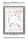
3.2 Power Supply (S2, JP: 8, 15, 16, 17, 22)
The on-board voltage regulator provides stabilized 5V
*
1
and 3.3V supplies to the MCU
*
1
and
peripherals. Even though they are thermally protected against overload, care must be taken
when supplying current for additional circuitry.
The LIN Vs line can be connected directly to the input supply of the board by jumpers. In this
case, the input voltage to the board has to be suitable for the connected bus devices (mostly
around 12V). Since there is a protection diode between Vin and Vs, it is not possible to
power the board over the LIN bus.
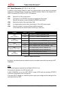
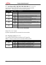
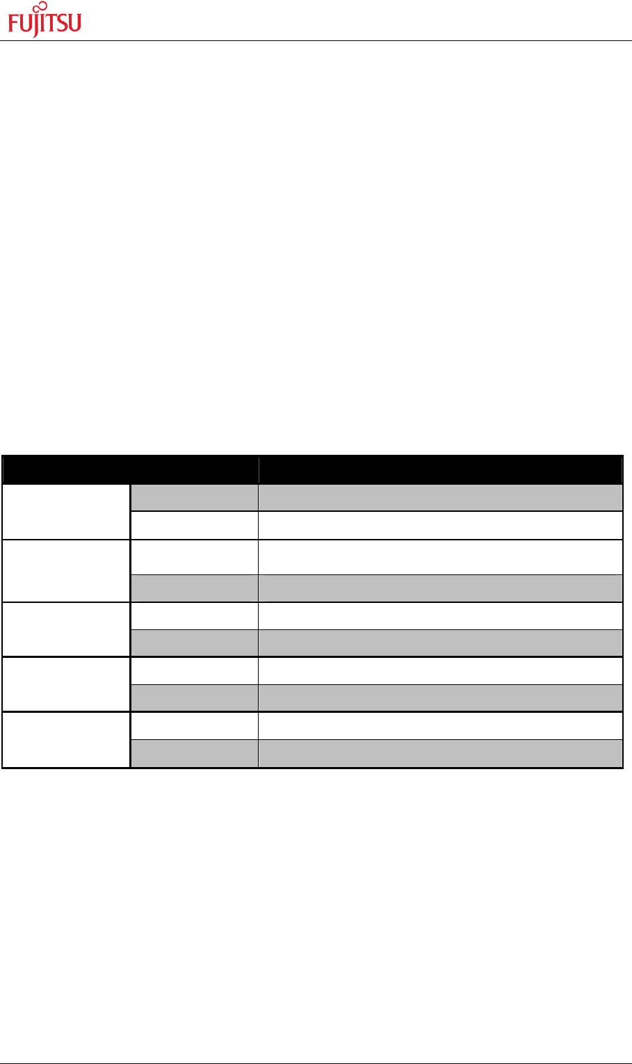
S2 Power Switch
JP8 Core power supply stabilization capacitor
JP15 Selects the power supply voltage for the microcontroller
For SK-96370-144PMC-GDC use only 3.3V, because of the external memory
JP16 Connects the power supply voltage to the microcontroller. An ampere meter can be
used instead for power consumption measurement.
JP17 Selects the Stepper Motor Driver Voltage (3.3V or 5V)
JP22 Jumper to override the power switch S2
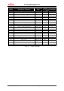
Jumper Setting Description
Closed An external capacitor is connected
JP8
(C-pin)
Open An external capacitor is not connected
1 - 2
Power supply (VCC) for MCU is set to 5V
(Not allowed for SK-96370-144PMC-GDC)
JP15
*1
(MCUVCC)
2 - 3 Power supply (VCC) for MCU is set to 3V3
1 - 2 MCU is disconnected from VCC
JP16
(MCUVCC)
2 - 3 MCU is connected to VCC
1 - 2 SMC (DVCC) supply voltage is set to 5V
JP17
(DVCC)
2 - 3 SMC (DVCC) supply voltage is set to 3.3V
Closed Board is always switched on
JP22
(Mains)
Open Board power is controlled by switch S2
Table 3-2: Power Supply Configuration
By default, all Board supplies are set to 3.3V.
*1
For SK-96370-144PMC-GDC use only 3.3V, because of the external memory