


SK-96370-144PMC-GDC User Guide
Chapter 4 Connectors
FMEMCU-UG-960014-10 - 28 - © Fujitsu Microelectronics Europe GmbH
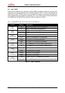
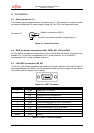
4.7 Alarm Comparator Connector (J2)
On the Connector J2 the adjusted analog voltage of potentiometer RP2 can be measured.
This voltage is used for the alarm comparator ALARM0 or analogue input AN8 on pin 28.
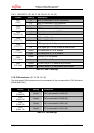
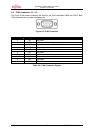
4.8 External Supply Voltage Vin (J3)
This connector is connected to the external supply voltage (Vin).
4.9 Vcc 5 Volts (J4)
On this connector the VCC5V supply can be measured.
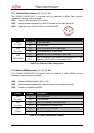
4.10 Vcc 3.3 Volts (J5)
On this connector the VCC3V3 supply can be measured.
4.11 Vcc 2.5 Volts (J9)
On this connector the VCC2V5 supply can be measured.
4.12 Vcc 1.8 Volts (J10)
On this connector the VCC1V8 supply can be measured.
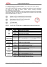
4.13 LIN Bus Inhibit (J6)
To this connector the INH pin of the LIN0 transceiver is connected.
4.14 LIN Bus Inhibit (J11)
To this connector the INH pin of the LIN1 transceiver is connected.
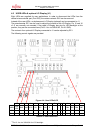
4.15 VCC Connector (J7)
On this connector the VCC supply (see chapter 3.2) can be measured.
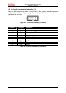
4.16 GND Connector (J8)
Ground reference terminal GND.