


SK-96370-144PMC-GDC User Guide
Chapter 3 Jumpers and Switches
FMEMCU-UG-960014-10 - 18 - © Fujitsu Microelectronics Europe GmbH
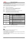
3.6 Reset Generation (JP: 33, 41, 46, 47, 48)
In addition to the internal Power-On reset, the microcontroller can be reset by an external
reset circuit (Voltage Monitor) and also by a RS232 interface. Refer to the chapter ‘LIN /
UART Connectors (X5 or X9)’ for DTR / RTS selection.
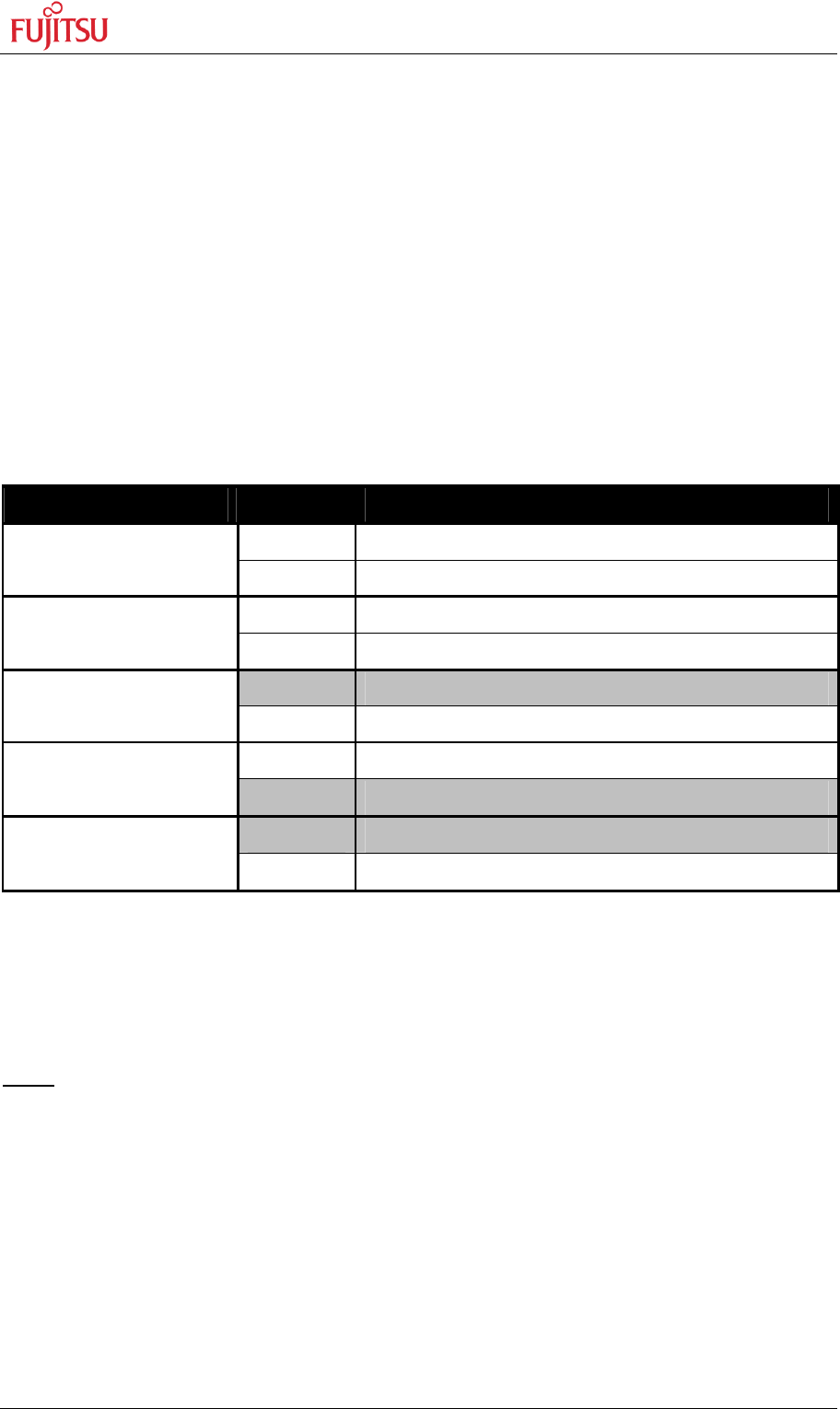
JP33 Selects X5 or X9 as reset source.
JP41 The signal on the DTR/RTS line can be negated with this jumper.
Remove the jumper in order to disable the RS232 reset circuit.
JP46 Selects the mode of the reset button SW6.
JP47 A voltage supply monitor allows monitoring of 1V8 or 2V5 power supply.
JP48 Open this jumper if no external Reset shall be generated.
In this case only the internal reset is active (e.g.: power-on).
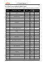
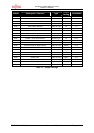
Jumper Setting Description
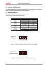
1-2 X5 (UART0) is used to generate Reset
JP33
(UART RESET)
2-3 X9 (UART2) is used to generate Reset
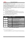
1-2 No polarity inversion for the DTR/RTS signal
JP41
(DTR / DTRx)
2-3 Polarity inversion for the DTR/RTS signal
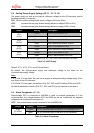
1-2 Reset is applied immediately when SW6 is pressed
JP46
(Reset imm./delayed)
2-3 Reset is applied when SW6 is pressed > 2sec
1-2 The voltage supply monitor observes 1V8
JP47
(Monitor 1V8 / 2V5)
2-3 The voltage supply monitor observes 2V5
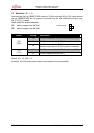
Closed External reset generation is active
JP48
(RST MCU)
Open No external reset generation
Table 3-5: Reset Connection
By default, the external reset is enabled and set to immediate reset while the reset by UART
is disabled.
Note:
While a reset signal is asserted the red Reset-LED LD13 is lit.
During normal operation, this LED should be off!
If JP41 (DTR/DTRx) is set, the UART RESET jumper (JP33) and the according DTR/RTS
(JP23 and JP38) jumper have to be set, too.
If the reset LED is steadily on, check the power supply input voltage and the settings for the
reset-generation by UART.