


SK-96370-144PMC-GDC User Guide
Chapter 3 Jumpers and Switches
© Fujitsu Microelectronics Europe GmbH - 23 - FMEMCU-UG-960014-10
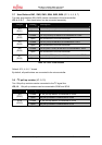
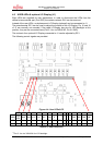
3.13 Graphic Display Controller interface (JP: 54, 55, 56, 57, 58, 60, 85, 86)
The SK-96370-144PMC-GDC provides the external bus interface on the two connectors
X10 and X11 in order to support Graphic Display Controller sub-boards,
e.g.: CREMSON-STARTERKITLIME.
Take care of proper jumper settings, in case those external sub-boards will be connected.
Some signals, like A22, CS2 and CS3, are shared with the on-board FLASH and SRAM
memory (see also chapter 3.11 and 3.12).
JP54 Address line A24 is not supported by the microcontroller
JP55 Address line A25 is not supported by the microcontroller
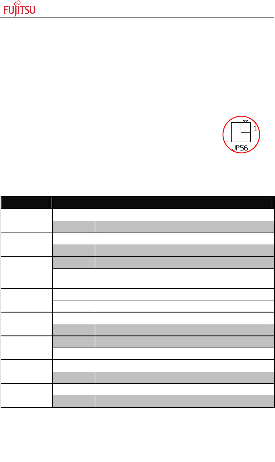
JP56 Signal sharing of A22 and CS2 for FLASH and GDC
JP57 Chip selection for external sub board
JP58 1.8V power supply
JP60 Mains power supply
JP70, 71 The port P08_0 may be used e.g. to generate manual reset on the sub board.
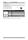
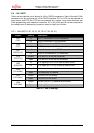
Jumper Setting Description
Open Address line A24 is floating JP54
(A24)
Closed Address line A24 is connected to GND
Open Address line A25 is floating JP55
(A25)
Closed Address line A25 is connected to GND
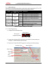
2-4 Address line A22 is connected to the FLASH
JP56
(GDC/FLASH)
1-2
3-4
CS2 is connected to the connector (see jumper JP57), too
Address A22 of FLASH is connected to GND
1-2 Connect CS3 to the connector JP57
(CS2/CS3)
2-3 Connect CS2 to the connector
Open 1.8V is not supplied to connector X11B JP58
(1V8)
Closed 1.8V is supplied to connector X11B
Open Mains is not connected to connector X11B JP60
(Mains)
Closed Mains is connected to X11B
Open P08_0 is not connected to X11A_11A JP70
(GLRST)
Closed P08_0 is connected to X11A_11A
Open P08_0 is not connected to X11A_12A JP71
(FLRST)
Closed P08_0 is connected to X11A_12A
Table 3-12: Graphic Display Controller interface
2
3
4