


SK-96370-144PMC-GDC User Guide
Chapter 3 Jumpers and Switches
© Fujitsu Microelectronics Europe GmbH - 21 - FMEMCU-UG-960014-10
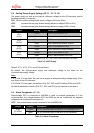
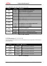
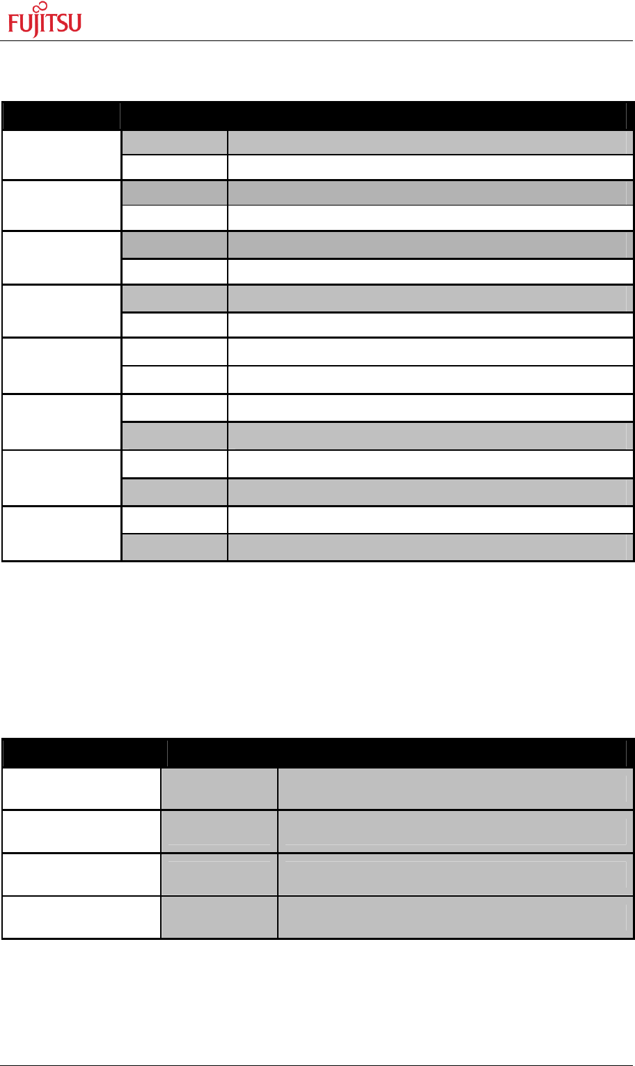
3.9.2 LIN-UART 2 (JP: 36, 37, 38, 39, 40, 42, 43, 45)
Jumper Setting Description
1-2 SIN2 is connected to RS232 transceiver
JP37
(RXD)
2-3 SIN2 is connected to LIN transceiver
1-2 SOT2 is connected to RS232 transceiver
JP39
(TXD)
2-3 SOT2 is connected to LIN transceiver
1-2 X9 pin 2 is connected to RS232 transceiver
JP40
(RS232/LIN)
2-3 X9 pin 2 is connected to LIN transceiver
Closed RTS and CTS of X9 are connected
JP36
(RTS-CTS)
Open RTS and CTS of X9 are not connected
1-2 DTR signal (pin 6 of X9) is used as reset source
JP38
(DTR/RTS)
2-3 RTS signal (pin 7 of X9) is used as reset source
Closed LIN transceiver for X5 is enabled
JP43
(LIN enable)
Open LIN transceiver for X5 is disabled
Closed LIN-UART2 is LIN Master
JP45
(LIN master)
Open LIN-UART2 is LIN Slave
Closed LIN bus (X9 pin 1) is powered by the board
JP42
(LIN Vbat)
Open LIN bus (X9 pin 1) is not powered by the board
Table 3-8: UART2 Settings
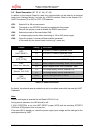
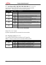
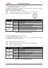
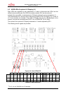
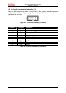
3.10 CAN interfaces (JP: 24, 26, 34, 35)
Two high-speed CAN-transceivers can be connected to the microcontroller’s CAN interfaces
(CAN0 and CAN1).
Jumper Setting Description
JP24
(CAN0 RX)
Closed RX0 is connected to CAN0 (X6)
JP26
(CAN0 TX)
Closed TX0 is connected to CAN0 (X6)
JP34
(CAN1 RX)
Closed RX1 is connected to CAN1 (X8)
JP35
(CAN1 TX)
Closed TX1 is connected to CAN1 (X8)
Table 3-9: CAN Settings