


SK-96370-144PMC-GDC User Guide
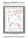
Chapter 3 Jumpers and Switches
© Fujitsu Microelectronics Europe GmbH - 17 - FMEMCU-UG-960014-10
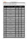
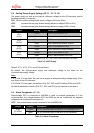
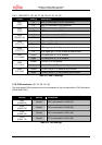
3.4 Analog Power Supply Voltage (JP: 11, 12, 13, 14)
The power supply as well as the positive reference voltage for the A/D-converter can be
provided internally or externally.
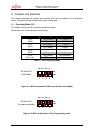
JP11, JP14 connects analog power supply voltages (AVcc and AVss)
JP12 connects the low pass filtered analog reference voltage AVRH to AVcc
JP13 connects the low pass filtered analog reference voltage AVRL to AVss
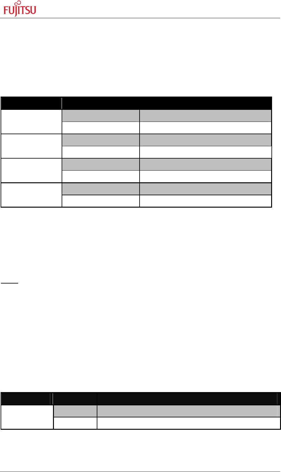
Jumper Setting Description
Closed AVcc is connected to Vcc
JP11
(AVcc)
Open AVcc is disconnected from Vcc
Closed AVRH is connected to AVcc
JP12
(AVRH)
Open AVRH defined by resistor network
*
1
Closed AVRL is connected to AVss
JP13
(AVRL)
Open AVRL defined by resistor network
*1
Closed AVss is connected to GND
JP14
(AVss)
Open AVss is disconnected from GND
*
1
By default the resistor network (R16, R17, R20, R21) is not mounted on the board
Table 3-3: ADC Supply
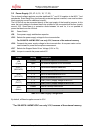
Default: JP11, JP12, JP13, and JP14 are closed
By default, the A/D-converter supply and reference voltage is the same as the
microcontroller supply voltage.
Note:
If JP11 and JP14 are open, the user has to supply an adequate analog voltage supply (AVcc
and AVss) to the A/D-converter.
If JP12 and JP13 are open, the resistors R16, R17, R20, and R21 define AVRH and AVRL.
By default the resistor network (R16, R17, R20, and R21) is not mounted on the board.
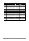
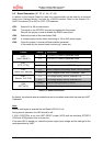
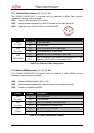
3.5 Alarm Comparator (JP: 85)
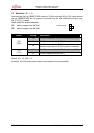
Potentiometer RP2 is connected to ALARM0 in order to evaluate comparator 0 of the
microcontroller. Any voltage between VCC and GND can be set. Additionally the adjusted
voltage can be measured at connector J2.
JP78 One potentiometer can be connected to the ALARM0/AN8
Jumper Setting Description
Closed Pin 26 (ALRAM0/AN8) of the MCU is connected to RP2
JP85
(ALARM0)
Open Pin 26 (ALRAM0/AN8) of the MCU is not connected
Table 3-4: Alarm Comparator