


SK-96370-144PMC-GDC User Guide
Chapter 5 Programming the internal Flash memory
FMEMCU-UG-960014-10 - 30 - © Fujitsu Microelectronics Europe GmbH
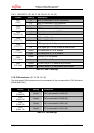
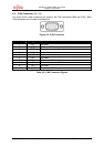
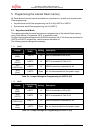
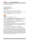
ON
OFF
DIP-Switch S1
(Programming Mode
)
MD0 MD1 MD2 nc
1 2 3 4
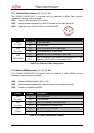
5.1.3 Reset (optional)
Depending on the programming software a reset signal might be generated by RTS or DTR
line. In order to use this optional feature additional jumper have to be set:
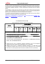
Jumper Programming
UART
Setting Description
1-2
DTR signal of X5 is used as reset source JP23
(DTR/RTS)
UART0
2-3
RTS signal of X5 is used as reset source
1-2
DTR signal of X9 is used as reset source JP38
(DTR/RTS)
UART2
2-3
RTS signal of X9 is used as reset source
1-2
LIN-UART 0 (X5) is used to generate reset JP33
(RESET A/B)
UART0 or
UART2
2-3
LIN-UART 2 (X9) is used to generate reset
1-2
No negation for the DTR/RTS signal JP41
(DTR / DTRx)
UART0 or
UART2
2-3
DTR/RTS signal is negated
Table 5-3: Jumper Settings for reset signal
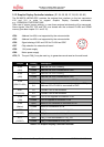
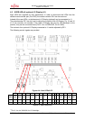
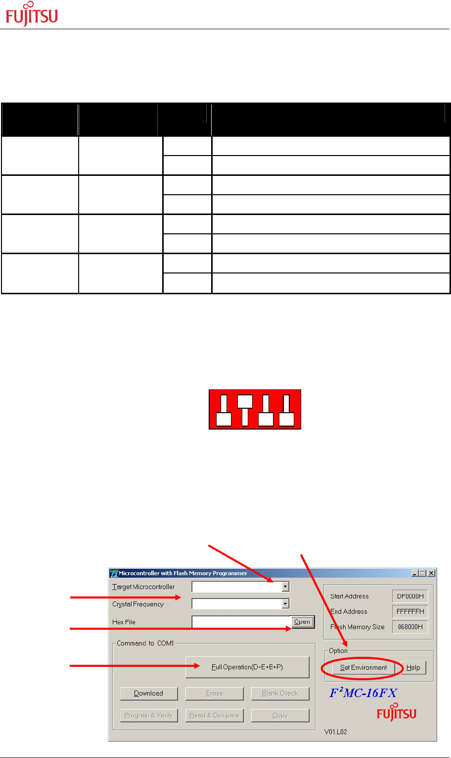
5.1.4 Flash Programming
1) Configure the microcontroller mode:
2) Connect the configured UART (see above) to your serial PC communication port.
A straight 1:1 cable connection has to be used.
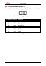
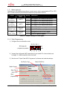
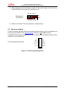
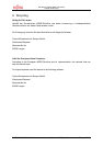
3) Start the tool “Fujitsu Flash MCU Programmer” software and make the settings:
Set Device Type Select COM Port
Start
programming
Open Source
(MHX
-
File)
Select Crystal
Application.MHX
4 MHz
MB96F3
79
R/Y