


SK-96370-144PMC-GDC User Guide
Chapter 5 Programming the internal Flash memory
© Fujitsu Microelectronics Europe GmbH - 29 - FMEMCU-UG-960014-10
5 Programming the internal Flash memory
All Flash devices have an internal bootloader for asynchronous- as well as for synchronous-
Flash-programming:
< Asynchronous serial Flash programming via X5 or X9 (UART0 or UART2)
< Synchronous serial Flash programming via X4 (UART3)
5.1 Asynchronous Mode
This chapter describes the serial asynchronous programming of the internal Flash memory
using ‘Flash Memory Programmer 16FX’ in automatic mode.
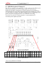
For serial asynchronous programming SUB-D9 connectors X5 or X9, which are connected to
UART0 and UART2 respectively, can be used on the starter kit.
The following jumper settings are necessary:
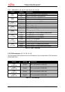
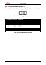
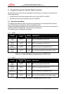
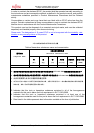
5.1.1 Uart0
Jumper
Programming
UART
Setting Description
JP21
(SIN0)
UART0 1-2 SIN0 is connected to RxD of X5
JP25
(SOT0)
UART0 1-2 SOT0 is connected to TxD of X5
JP27
(RS232/LIN)
UART0 1-2 RS232 transceiver is selected for X5
JP28
(Vbat)
UART0 Open X5-1 is disconnected from the power supply
Table 5-1: Jumper Settings for Programming via UART 0 (X5)
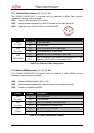
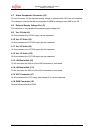
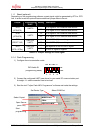
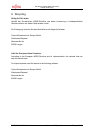
5.1.2 Uart2
Jumper
Programming
UART
Setting Description
JP37
(SIN2)
UART2 1-2 SIN2 is connected to RxD of X9
JP39
(SOT2)
UART2 1-2 SOT2 is connected to TxD of X9
JP40
(RS232/LIN)
UART2 1-2 RS232 transceiver is selected for X9
JP42
(Vbat)
UART2 Open X9-1 is disconnected from the power supply
Table 5-2: Jumper Settings for Programming via UART 2 (X9)