


SK-96370-144PMC-GDC User Guide
Chapter 3 Jumpers and Switches
FMEMCU-UG-960014-10 - 16 - © Fujitsu Microelectronics Europe GmbH
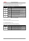
3.3 Subclock (JP: 1, 2)
Some devices like e.g. MB96F37xRW support a 32 kHz sub-clock (X0A, X1A), other devices
like e.g. MB96F37xRS do not support a sub-clock but will offer additional port-pins (e.g.
P04_0, P04_1) instead.
Please check the related datasheet.
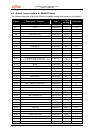
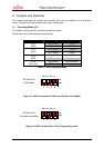
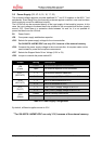
JP1: defines usage of pin 69 (X1A)
JP2: defines usage of pin 68 (X0A)
Jumper Setting Description
1-4 Pin 68 is connected to the 32 kHz sub-clock (X0A)
2-4 Pin 68 is used as port pin P04_0
JP2
(X0A)
3-4
Pin 68 is connected to GND (in case that subclock-
device is used, but no 32 kHz crystal is connected)
1-2 Pin 69 is connected to the 32 kHz sub-clock (X1A)
JP1
(X1A)
2-3 Pin 69 is used as port pin P04_1
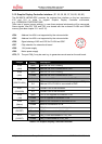
Default: JP1: 1-2, JP2: 1-4
By default, the 32 kHz sub-clock-crystal is connected to the microcontroller.
4
3
1
2
Pin
-
out JP2: