


SK-96370-144PMC-GDC User Guide
Chapter 4 Connectors
FMEMCU-UG-960014-10 - 24 - © Fujitsu Microelectronics Europe GmbH
4 Connectors
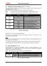
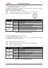
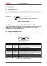
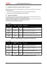
4.1 Power connector (X7)
The following figure shows the power connection jack X7. This connector is used to connect
an external unregulated DC power supply voltage (9V-15V DC) to the evaluation board.
Connector X7:
Figure 4-1: Power Connector
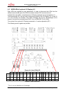
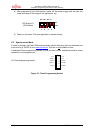
4.2 MCU pin header connectors (X20A, X20B, X21, X22 and X23)
All pins (except oscillator and supply pins) of the microcontroller are directly connected to pin
headers. Pin 1 of the MCU corresponds to Pin 1 of the connector. Pin 2 of the MCU
corresponds to Pin 2 of the connector, and so on.
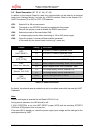
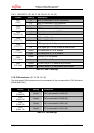
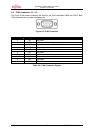
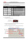
4.3 LIN-UART connectors (X5, X9)
Two 9-pin D-Sub female connectors are used for the serial interfaces. Note that X5 and X9
are shared between the RS232- and LIN transceivers and must be configured to the desired
functionality (refer to chapter 3.9 for details).
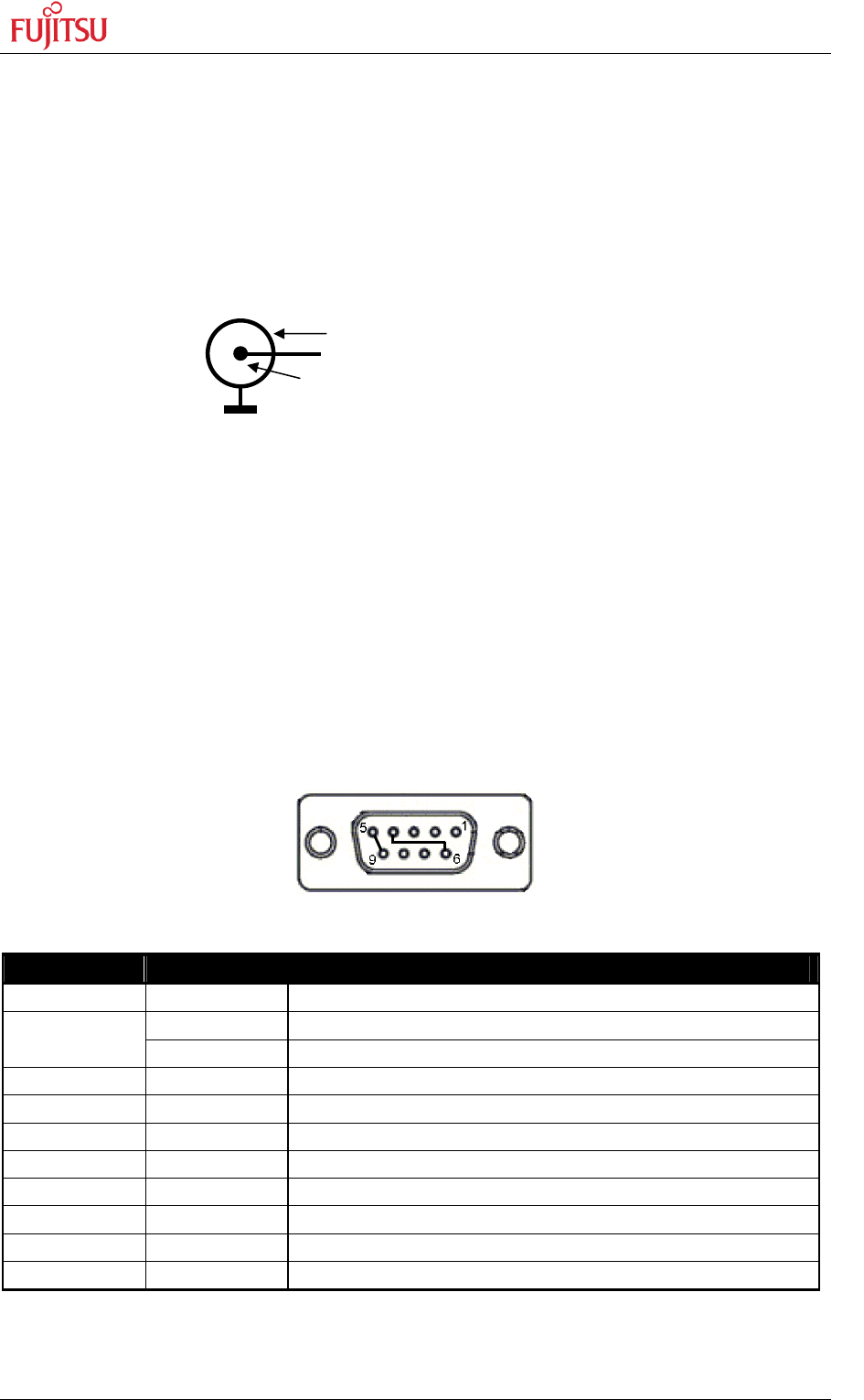
Figure 4-2: UART Connector
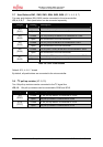
Pin Number Pin Signal Description
1 +VBat Power from / to LIN bus
TXD RS-232 transmit output
2
LIN Bi-directional LIN-interface bus
3 RXD RS-232 receive input
4 DTR Connected to DSR (pin 6)
5 GND Ground normally used for RS232 connection
6 DSR Connected to DTR (pin 4)
7 RTS Can be connected with CTS by jumper
8 CTS Can be connected with RTS by jumper
9 LGND Ground normally used for LIN connection
Shield GND Ground
Table 4-1: UART Connector Signals
Shield is connected to GND (-)
Center is connected to positive voltage supply (+)
+