


SK-96370-144PMC-GDC User Guide
Chapter 3 Jumpers and Switches
© Fujitsu Microelectronics Europe GmbH - 19 - FMEMCU-UG-960014-10
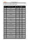
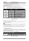
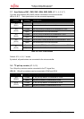
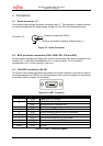
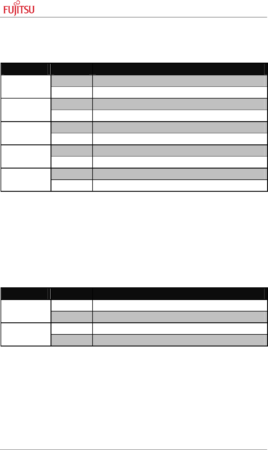
3.7 User Buttons SW1, SW2, SW3, SW4, SW5, SW6 (JP: 3, 4, 5, 6, 7)
Five user push buttons (SW1-SW5) can be connected to the microcontroller.
JP3, 4, 5, 6, 7 Each push button can be connected separately.
Jumper Setting Description
Closed Pin 139 (INT0/NMI) of the MCU is connected to “SW1”
JP3
(SW1)
Open No connection to the microcontroller
Closed Pin 19 (FRCK0) of the MCU is connected to “SW2”
JP4
(SW2)
Open No connection to the microcontroller
Closed Pin 22 (TIN1) of the MCU is connected to “SW3”
JP5
(SW3)
Open No connection to the microcontroller
Closed Pin 20 (IN0/TTG4/0) of the MCU is connected to “SW4”
JP6
(SW4)
Open No connection to the microcontroller
Closed Pin 21 (IN1/TTG5/1) of the MCU is connected to “SW5”
JP7
(SW5)
Open No connection to the microcontroller
Table 3-6: User Push Buttons
Default: JP3, 4, 5, 6, 7 closed
By default, all push-buttons are connected to the microcontroller.
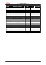
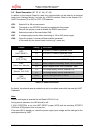
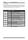
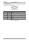
3.8 I
2
C pull-up resistor (JP: 9, 10)
Two 10k pull-up resistors can be connected to the I
2
C signal line.
JP9, 10 10k pull-up resistors can be connected to SDA0 and SCL0
Jumper Setting Description
Closed A 10k pull-up resistor is connected to SDA0
JP9
(SDA0)
Open No pull-up resistor is connected to SDA0
Closed A 10k pull-up resistor is connected to SCL0
JP10
(SCL0)
Open No pull-up resistor is connected to SCL0