


12
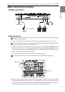
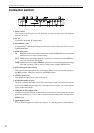
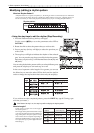
2. Front and rear panel
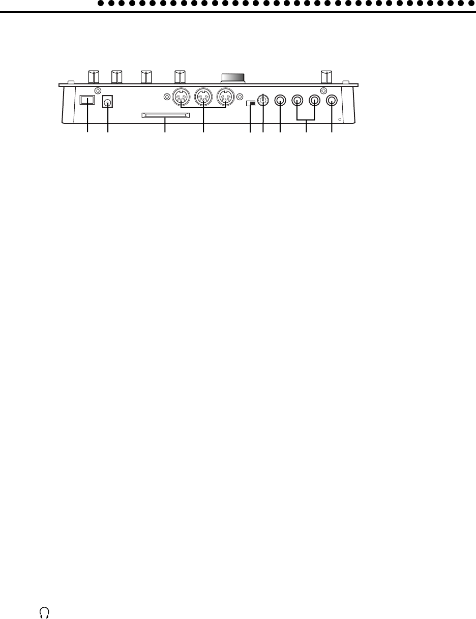
Connector section
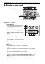
1 23456789
1. Power switch
This switch turns the power on/off. Each time you press it, the power will alternate
between on or off.
2. DC 9V
Connect the included AC adapter here.
3. SmartMedia
TM
slot
A SmartMedia
TM
card can be inserted into this slot. Use this when you wish to save or
load ES-1mk
II
data.
4. MIDI connectors
IN MIDI data is received at this connector to control the ES-1mk
II
from an external
MIDI device or to receive a data dump.
OUT MIDI data is transmitted from this connector to control an external MIDI de
vice or to transmit a data dump.
THRU MIDI data received at the MIDI IN connector is re-transmitted without change
from this connector. This is used to "daisy-chain" multiple MIDI devices.
5. MIC/LINE (gain select switch)
This switches the input gain of the audio input. When a mic is connected, set this to
the MIC position. Otherwise, set this to the LINE position.
6. LEVEL (input level)
This adjusts the input level of the audio input.
7. ST./MONO (audio in jack)
This jack is used for the audio in part. The sound that is input here will be used as the
sound of the Audio In part select key. If the input source is stereo, use a stereo phone
jack to make connections.
8. L/MONO, R (line output) jacks
Connect your audio cables from these jacks to your mixer or powered monitor system
(powered speakers) etc. If you wish to make monaural connections, connect the L/
MONO jack.
9. (headphone jack)
A set of stereo headphones fitted with a stereo 1/4” jack plug can be connected here.