


2 - 6
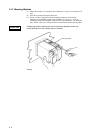
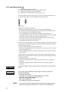
2.2.3 Input Signal Wiring
!
(1) Turn off the recorder power switch.
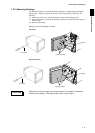
(2) Remove the transparent cover for the input signal terminals.
(3) Connect the input signal wires to the terminals.
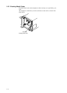
(4) Attach the cover on the terminals, and secure the screws.
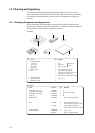
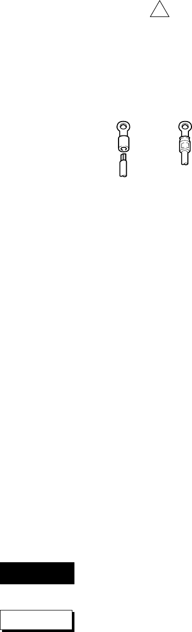
It is recommended to use the crimp-on lugs (for 4 mm screws) with insulation sleeves
for lead wire ends, but they are not required for thermocouples (TC).
Crimp-On Lugs
Suggestions to minimize noise pickup:
• Separate the measuring-signal wires from power lines and grounding lines.
• It is desirable that the measuring object is not a noise source; if not, insulate it from
the measuring-signal wires and ground the object.
• It is recommended to use shielded wires to minimize noise pickup from an
electrostatic induction source. The shields are connected to the recorder’s grounding
terminal, if necessary. In that case, avoid two-point grounding.
• To minimize the noize from an electrostatic induction noise, twist the measuring
wires (a pair of wires) in short and equal intervals.
• The grounding line must have low resistance.
In case of using a thermocouple (TC), the recorder is equipped with a reference junction
compensator, so the ambient temperature around the recorder’s terminal board should
be kept as stable as possible.
• Cover the input terminals with the transparent cover.
• Do not use a large-diameter wire (cross sectional area of more than 0.5 mm
2
) because
it has a large radiation rate.
• Keep the ambient temperature as stable as possible; start/stop of a nearby fan affects
the temperature.
If input signal wires are connected to two or more receivers with parallel connection,
measured values sometimes affect each other. The following notes should be observed
for parallel connection:
• Ground each receiver at the same point.
• Do not turn on/off the power of a receiver while other receivers are in measuring
operation.
• A resistance temperature detector (RTD) cannot be used essentially in parallel
connection.
To prevent an electric shock, ensure the main power switch is turned off when
wiring.
Do not apply inputs exceeding the rated range as follows to prevent the
recorder from damage:
• Maximum input voltage
±10 V DC for TC, and for the voltage range of 2 V DC or less
±30 V DC for the voltage range of 6 to 20 V DC
• Maximum common mode voltage
250 V AC rms (50/60 Hz)
• The installation of each input is Category II.
NOTE • To prevent an emission of electromagnetic disturbances, separate the input
wires from the other wires at least 0.1 m. Over 0.5 m is recommended.
WARNING
CAUTION