


4 - 15
4. DAILY OPERATION/MAINTENANCE
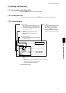
4.8 Maintenance
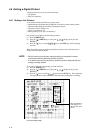
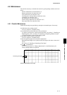
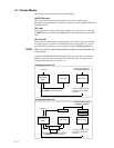
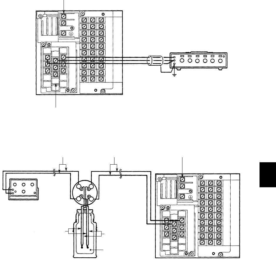
Three lead wires should have the
same resistance values.
Power terminal
Input terminals
(for RTD)
Decade resistance box
L
N
1
2
3
b
B
A
Temperature Signal as RTD for Pen model
(for Dot-printing model, the wire connection exchanges between the terminal B and b.)
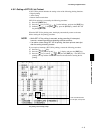
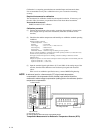
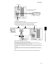
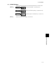
Temperature Compensation for Thermocouple Signal
Power terminals
(reference junction compensator Model TRCIII)
Thermocouple wires or extension wiresCopper wires
DC voltage standard
Ice pieces packed to
maintain the
temperature at 0ßC
Thermocouple wires
Copper wires
L
N
1
2
3
—
+
+
—
Meter
Couple
+
—
+
—
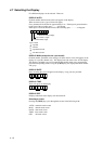
Reference Junction Compensation for Thermocouple Input
A DC voltage generated by a thermocouple differs from a value calculated from the table of thermo-
electromotive force (EMF) because the table is based on the 0˚C reference temperature but the temperature at
the recorder input terminal is generally equal to the room temperature.
The recorder measures the temperature at the input terminal for compensation; when the input terminals are
shorted (equivalent to 0˚C of the thermocouple in the EMF table), the recorder indicates the temperature at the
input terminal.
For calibrating a recorder, an input voltage after the compensation (after subtraction of the compensating
voltage) should be applied to the recorder; an example is shown in (thTRCIII reference junction compensator
is used).
Reference Temperature Compensating Connection for Pen model (same as Dot-printing model)