


13
Panel Descriptions
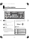
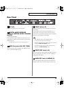
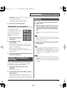
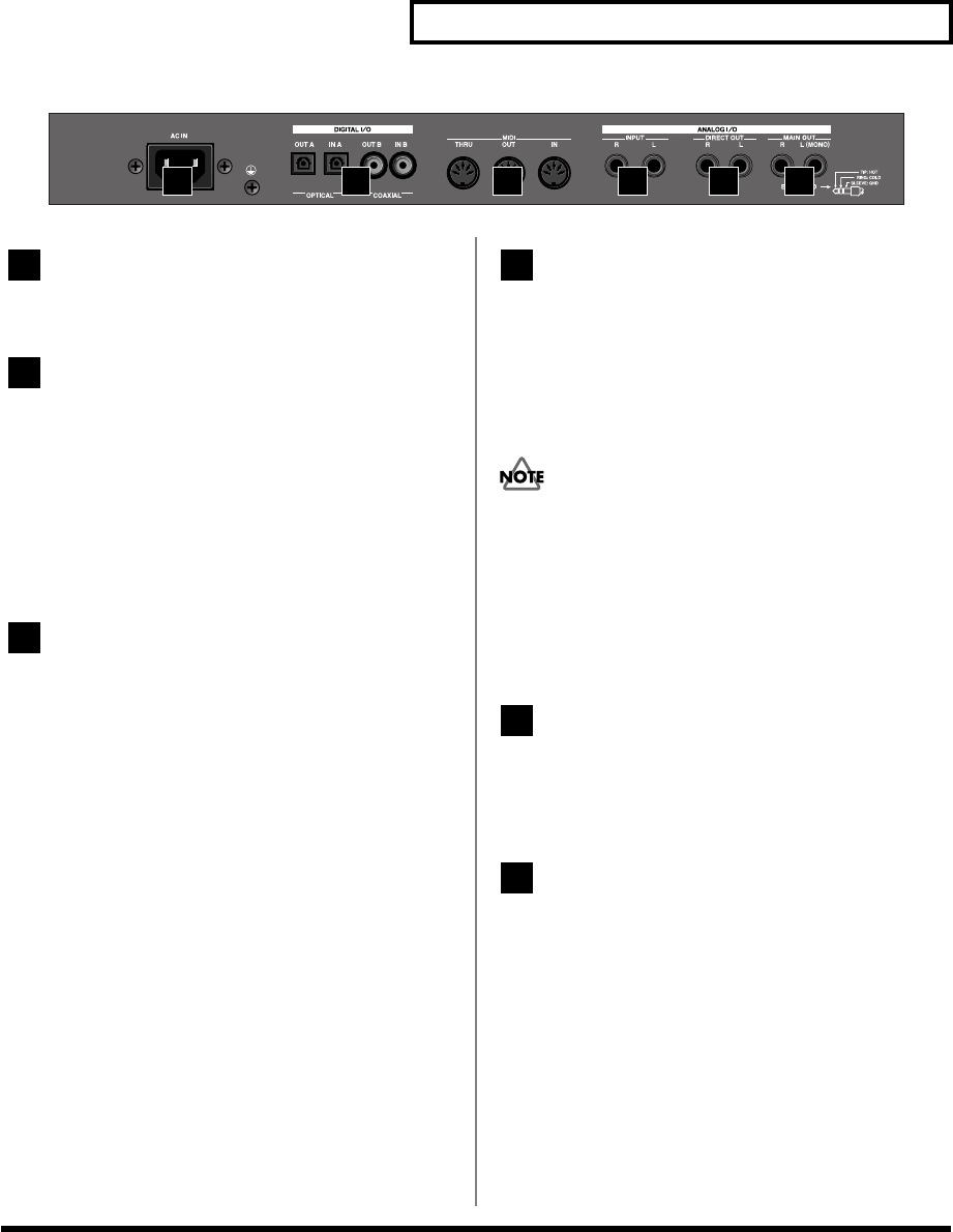
Rear Panel
AC Inlet
Connect the included power cord to this inlet.
DIGITAL AUDIO INTERFACE
Connector (OPTICAL IN/OUT, COAXIAL
IN/OUT)
(conforming to IEC60958).
These connectors output a digital audio signal (stereo). The
output signal is identical to the signal that is output from the
MAIN OUT jacks.
* The digital input connectors are not used with the VC-2.
MIDI Connectors (IN, OUT, THRU)
These connectors can be connected to other MIDI devices to
receive and transmit MIDI messages.
INPUT Jacks (L, R)
An external audio source can be connected to these jacks for
external input.
If you’re playing a patch whose patch algorithm (p. 8) is
Processor Type 1 or Processor Type 2, connect an external
audio source (e.g., keyboard or CD player) to the V-Synth XT’s
“INPUT L” jack, and input an audio signal.
The “INPUT R” jack is not used with the VC-2.
* Connect your mic to the front panel MIC jack.
* The audio signal received via the INPUT jacks can be switched
on/off by the
INPUT Jack Switch
(p. 38).
* The gain of the audio signal received via the INPUT jacks is
adjusted by the
INPUT Jack Gain
(p. 38).
DIRECT OUT Jacks (L, R)
These jacks output the audio signal from the MIC jack before it
has passed through the pre-effect (p. 25). The L and R jacks
will output the same signal.
MAIN OUT Jacks (L (MONO), R)
These jacks output the audio signal to the connected mixer/
amplifier system in stereo. For mono output, use the L jack.
1 2 3 4 5 6
1
2
3
4
5
6
vc2_for_XT_e1 13 ページ 2005年3月8日 火曜日 午後4時52分