


26
Creating/Editing Patches (Patch mode)
For the parameters of the noise supressor, refer to the
explanation of
NS-COMP
.
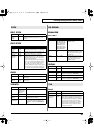
LIMITER
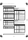
NOISE SUP
Noise suppressor settings can be made.
For the parameters of the three-band equalizer, refer to
the explanation of
OFF
. (p. 25)
NOISE SUPRESSOR
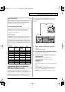
You can go to the top screen by touching
<Carrier>
in the
lower part of the screen.
Patches whose patch algorithm is
Poly PShift
do not
have this screen.
The carrier screen will be different if the patch algorithm
is
Processor~
. Refer to “
Carrier Screen for Processor~
Patch Algorithms
” (p. 29).
OSC 1/OSC 2
The following parameters will be displayed if the oscillator
type is
Analog
.
The following parameters will be displayed if the oscillator
type is
PCM
.
Parameter
Value Explanation
Thres
(Threshold
Level)
-40–
0 dB
Specifies the level (threshold level) at
which the limiter will begin to function.
Attack (At-
tack Time)
0–127 Specifies the time from when the input
level exceeds the threshold level until the
limiter begins to operate.
Release
(Release
Time)
0–127 Specifies the time from when the input
level drops below the threshold level until
the limiter turns off.
Ratio 2:1–
INF:1
Specifies the compression ratio.
Level (Out-
put Level)
0–127 Adjusts the volume of the mic.
* This is linked with MIC Level in the top
screen.
Parameter
Value Explanation
Thres
(Threshold
Level)
-60–0 dB Specifies the level at which the noise
suppressor will begin to operate. When
the signal falls below the specified lev-
el, it will be muted.
Release
(Release
Time)
0–127 Specifies the time from when the noise
suppressor begins to operate until the
volume reaches 0.
Level (Out-
put Level)
0–127 Adjusts the volume of the mic.
* This is linked with MIC Level in the top
screen.
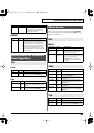
Carrier Screen
OSC
Parameter
Value Explanation
Wave
— Selects the wave.
* The available waves will depend on the
patch algorithm.
Level
0–127 Adjusts the output volume.
Pan L64–
0–63R
Specifies the pan of the patch. “L64” is far
left, “0” is center, and “63R” is far right.
Pulse
Width
-63–
+63
Specifies the amount by which the wave
shape will be modified.
SubOSC OFF,
-2,
-1,
0
The same wave will be layered.
OFF: No sound.
-2: The second wave will sound two oc-
taves below.
-1: The second wave will sound one octave
below.
0: The second wave will sound at the same
pitch.
SubLvl 0–127 Specifies the output volume of the second
wave.
Detune -63–
+63
Specifies the amount of detuning for the
second wave.
Parameter
Value Explanation
Wave
— Selects the wave.
* The available waves will depend on the
patch algorithm.
Level
0–127 Adjusts the output volume.
Pan L64–
0–63R
Specifies the pan of the patch. “L64” is far
left, “0” is center, and “63R” is far right.
Offset 0–15 Adjusts the precise point at which the
wave is to begin sounding.
vc2_for_XT_e1 26 ページ 2005年3月8日 火曜日 午後4時52分