


49
Effects List
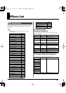
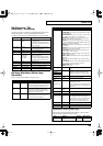
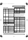
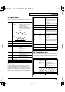
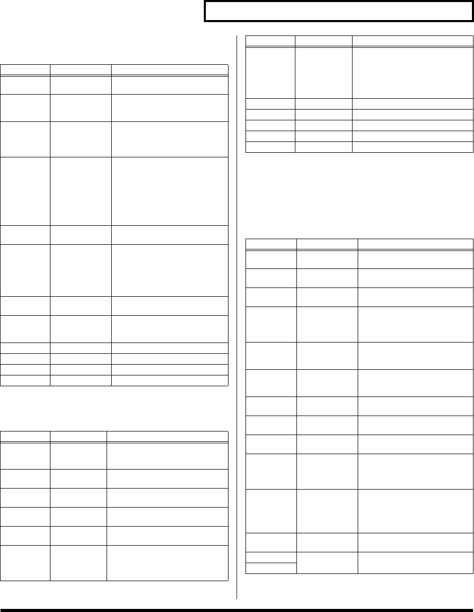
13: Reverse Delay
Adds the reverse of the input sound as the delay sound.
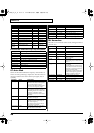
14: Vocal Echo
This effect simulates a karaoke echo.
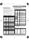
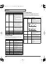
15: Band Pass Delay
This is a delay with a band pass filter (a filter that outputs only
a specified frequency range) on each of five delays. A phaser is
included before the delay. Phaser is an effect that adds a
phase-shifted sound to the original sound to create time-
varying change, modulating the sound.
Parameter
Value Description
Threshold
0–127 Specifies the input level at which
the delay will begin to apply.
Rvs Dly
Time
0–650 ms, note Specifies the delay time from the
original sound until the delay
sound is heard.
Rvs Feed-
back
-98– +98 % Adjusts the proportion of the re-
verse delay sound that is fed back
into the effect. Negative (-) set-
tings will invert the phase.
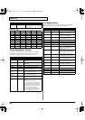
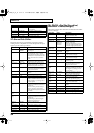
Low Damp
Freq
50–4000 Hz Adjusts the frequency below
which sound fed back to the effect
will be cut.
The Low Damp function damps
the low frequency band of the de-
lay sound quicker than other
bands, which makes for a clearer
delay effect.
Low Damp
Gain
-36–0 dB Degree of Low Damp
Hi Damp
Freq
2000–20000 Hz Adjusts the frequency above
which sound fed back to the effect
will be cut.
High Damp, by attenuating the
higher frequencies first, makes
the delay sound more natural.
Hi Damp
Gain
-36–0 dB Degree of High Damp
Balance DRY100:0WET–
DRY0:100WET
Volume balance between the di-
rect sound (DRY) and the effect
sound (WET)
Ps Low Freq 50–4000 Hz Frequency of the low range
Ps Low Gain -15– +15 dB Gain of the low range
Ps Hi Freq 2000–20000 Hz Frequency of the high range
Ps Hi Gain -15– +15 dB Gain of the high range
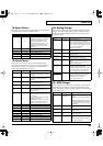
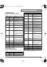
Parameter
Value Description
Delay Time
0–650 ms, note Adjusts the delay time from the di-
rect sound until the delay sound is
heard.
Pre LPF
Freq
500–15000 Hz,
THRU
Sets the filter’s cutoff frequency
(THRU: no filter is used)
Mod Rate 0.05–10.0 Hz,
note
Specifies the modulation speed of
the modulation effect.
Mod Depth 0–127 Specifies the modulation depth of
the modulation effect.
Diffusion 0–100 Specifies the spaciousness of the
delay sound.
Feedback -98– +98 % Adjusts the proportion of the delay
sound that is fed back into the ef-
fect. Negative (-) settings will in-
vert the phase.
Hi Damp
Freq
500–15000 Hz,
THRU
Adjusts the frequency above which
sound fed back to the effect will be
cut.
High Damp, by attenuating the
higher frequencies first, makes the
delay sound more natural.
Echo Level 0–127 Volume of the echo sound
Ps Low Freq 50–4000 Hz Frequency of the low range
Ps Low Gain -15– +15 dB Gain of the low range
Ps Hi Freq 2000–20000 Hz Frequency of the high range
Ps Hi Gain -15– +15 dB Gain of the high range
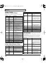
Parameter Value Description
Phaser Man-
ual
0–127 Specifies the center frequency at
which the sound is modulated.
Phaser Rate 0.05–10.0 Hz,
note
Specifies the frequency of modu-
lation.
Phaser
Depth
0–127 Specifies the depth of modula-
tion.
Phaser Reso-
nance
0–127 Specifies the amount of feedback
for the phaser.
Higher settings will give the
sound a stronger character.
Phaser Mix
Level
0–127 Specifies the volume of the
phase-shifted sound, relative to
the direct sound.
Delay Time 0–1300 ms, note Adjusts the delay time from the
direct sound until the each delay
sound is heard.
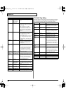
Fbk Dly
Time
0–1300 ms, note Adjusts the delay time for the
feedback sound.
Dly Time
Dev
0–1300 ms, note Specifies the differences in delay
time for each of the delay sounds.
Delay Level 0–127 Adjusts the volume of each delay
sound.
Delay Feed-
back
-98– +98 % Adjusts the proportion of the de-
lay sound that is fed back into the
effect. Negative (-) settings will
invert the phase.
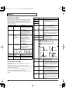
Delay Pan
Type
1–10 Specifies the pan of each delay
sound.
Ten settings are provided as vari-
ous panning combinations of the
delay sounds (see below).
BPF 1–5 Freq 50–20000 Hz Sets the center frequency for each
band pass filter (1–5).
BPF 1/2 Q 0.3–24.0 Specify the output bandwidth for
each band pass filter (1–5).
BPF 3/4/5 Q
Parameter
Value Description
vc2_for_XT_e1 49 ページ 2005年3月8日 火曜日 午後4時52分