


9
6.0 Cal=Trak Installation
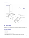
6.1 Attaching & Removing Flow Cells
The Sierra Cal=Trak accepts interchangeable cells for different flow ranges. If user tries to enter “Run Menu” prior to installing a flow cell,
the unit indicates “No Cell” and returns to the “Main Menu” after a 5 second delay.
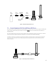
Attaching Flow Cells
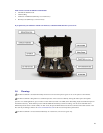
1. Position the selected flow cell into the electronics base opening with its silver Sierra Instruments label facing you.
2. Locate the guide pins; when the guide pins are engaged, press down firmly.
3. When the power is turned on, the base electronics will sense which cell is installed and display the appropriate units for that cell.
Removing Flow Cells
Grasp the flow cell firmly by the base of the cylinder and lift upward out of the base.
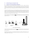
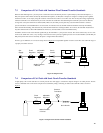
6.2 Connecting the Cal=Trak to a Flow Source
As the accuracy of the Cal=Trak is dependent upon the mechanical set-up (plumbing) of the device under test, it is useful to review the
basic operation of the calibrator prior to plumbing. Always remember the following important guidelines:
1. The accuracy of the Cal=Trak is dependent upon its source being stable. An unstable flow source may produce inconsistent
readings.
2. Sierra Instruments’ Cal=Trak is designed to be used at ambient pressures. This is easily accomplished by leaving the outlet of the
flow cell open to atmosphere for positive pressure installations or the inlet open to atmosphere for vacuum installations. If a vent
hose is required on the outlet fitting, a maximum pressure of 5 inches water column (0.18 psi or 12 mbar) above ambient is
acceptable. Exhaust pressure of more than this amount will add additional uncertainty to the flow measurements of Cal=Trak.
One way to reduce exhaust pressure is to increase the diameter of the vent line. Do not subject the Cal=Trak to a differential
pressure above 0.35 bar (5 PSI). In other words, the pressure drop across the Cal=Trak calibrator must not exceed 0.35 bar (5
PSI) or damage may occur. In vacuum scenarios, make certain that the pressure drawn across the Cal=Trak does not exceed 0.35
bar (5 PSI).
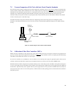
3. Flow direction is indicated by the arrow on the top of the flow cell. To use a pressure flow source, connect to the inlet fitting, or
to use a vacuum flow source, connect to the outlet fitting.
6.3 The Cal=Trak Measurement Cycle
Operation of a Cal=Trak is extraordinarily simple, and little training is required. However, any measurement interacts with the device being
calibrated to some degree. Often, these interactions are negligible. However, sometimes device interactions can seriously affect
measurement accuracy. Here we will explain what happens during a Cal=Trak measurement to aid in installing and using the instrument
appropriately.
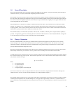
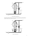
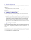
In its inactive state, the Cal=Trak will, like any device, exhibit a constant insertion pressure drop. At all but the highest flows, the pressure
drop is very small. In the inactive state, gas flows from the inlet to the outlet through the bypass valve (Figure 3
). When a measurement
cycle begins, the bypass valve closes, and the gas is directed into the cylinder, effectively inserting the piston in series with the gas flow,
allowing measurement. Timing commences after the piston has accelerated to the flow stream’s speed. At the end of the timed cycle, the
valve opens and the piston falls to its inactive position at the bottom of the cylinder.