


Direct Pro 24/96 Owner’s Manual
14
Direct Pro Interface Box - Front Input Volume Faders (cont’d)
23
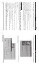
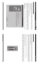
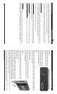
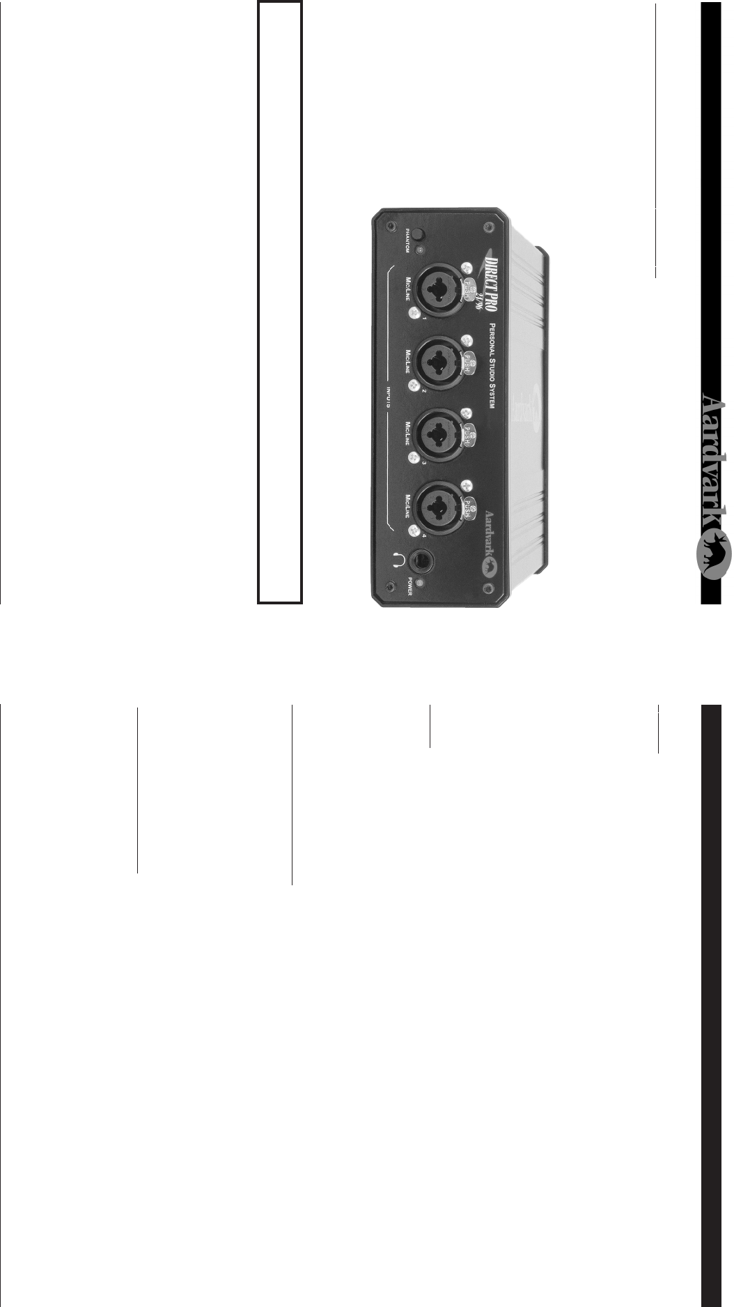
DIRECT PRO 24/96 INTERFACE BOX
The Direct Pro 24/96 interface box houses 4 shielded analog combo jack inputs, 6 shielded analog out-
puts, MIDI IN and MIDI OUT jacks, and a headphone jack for monitoring. Additional S/PDIF IN and S/PDIF
OUT jacks are on the Direct Pro 24/96 PCI host card.
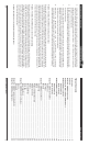
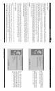
Front Panel
The Direct Pro 24/96’s front panel
consists of 4 analog combo jack
inputs, a headphone output, and
phantom power controls.
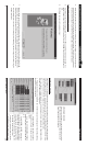
The combo jacks accept either 1/
4", or XLR mic connectors. The
1/4" inputs can accept either bal-
anced (+4dBu) or unbalanced (-
10dBV) signals. The XLR jacks
have built-in preamps with 60 dB
level trim. In addition, they are
equipped with an invariable 48V phantom power, allowing you to power professional condenser micro-
phones.
Phantom Power
The phantom power on/off switch activates phantom power for all 4 XLR inputs. Phantom power is not
delivered to the 1/4" input.
Headphone Jack
The headphone output enables you to monitor the audio without speakers.
Note: The headphone Jack is optimized for 60-150 ohm headphones. Headphones with impedance
higher than 150 ohm will sound softer.
WARNING: All line level connections MUST use the 1/4” input. XLR inputs are ONLY for microphones.
If the inputs are used incorrectly, damage may occur!
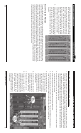
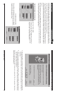
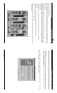
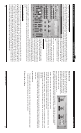
STEREO
This button on Channel 1 links all the effects and knobs of that strip with Channel 2, and the same is true
with Channel 3 & 4. This can also be thought of as a ‘Link’ button because every control on either strip
affects the other strip. There is no ‘master’ or ‘slave’ strip because changes on either strip will directly
make changes on the other.
The PAN slider at the bottom is automatically forced in the far Left and far Right positions. The PAN slider
is not ‘linked’ to the corresponding strip.
Only Channels 1 & 2 can be linked and Channels 3 & 4 can be linked. There is no way to ‘link’ all 4 input
strips together.
• MUTE: Turns off the channel’s signal entirely
• SOLO: The opposite of mute. Soloing an input channel will mute all other output channels. It will be the
only sudible channel.
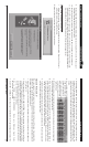
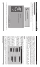
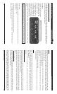
REC FX
This button allows flexibility in recording the effects that are on the Direct Pro 24/96 Control Panel input
strips. This button only affects the Compressor and EQ for that input channel strip. It does not allow
recording of the REVERB. For information on how to record our Reverb, refer to the Master Reverb sec-
tion of the manual.
Note: If you choose to record 96kHz audio, the Rec Fx button cannot be activated. All effects will be
disabled.
If the REC FX button is pressed
The EQ and Compressor (assuming they are not bypassed) that are on that channel strip will be recorded
into the corresponding recording device driver. This allows each of the 4 input channels to have their
own effects separately recorded onto 4 different tracks.
In this case, the digital peak meter shows the value of the wet signal that is being sent to the computer.
This is a post-fader meter so if you move the volume fader, the meter will move accordingly and affect the
level of the signal that is being recorded. It will also affect the level of that track as it is sent to the MONI-
TOR bus.
If this button is NOT pressed
The EQ and Compressor on the input channel strip can only be heard via the MONITOR bus should you
be listening or recording the MONITOR bus. The input device drivers 1,2 Direct Pro & 3,4 Direct Pro will
not record either the EQ or Compressor.
In this case, the digital peak meter shows the value of the dry signal that is being sent to the computer for
recording. The volume fader changes the volume of that track and sends it to the MONITOR bus. This
meter is before the fader (pre-fader) so if you move the volume fader, the meter will not be affected.