


Direct Pro 24/96 Owner’s Manual
15
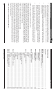
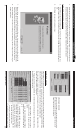
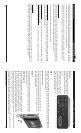
Input Volume Faders Direct Pro 24/96 Interface Box - Rear
22
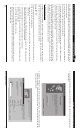
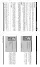
Rear Panel
The Direct Pro 24/96 rear panel has 6 ana-
log outs, MIDI in, MIDI out, and a 25 pin port
for connecting the interface box to the PCI
host card.
Analog outputs 1-4 are 1/4" jacks. They
can be used as balanced or unbalanced,
and output at the professional +4dBu level.
Outputs 5-6 are auxiliary RCA jacks, out-
putting at consumer level -10dBu.
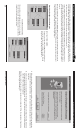
MIDI
MIDI in and out ports are provided for interfacing with other MIDI products, and producing MIDI time
code (MTC). This acts as a normal MIDI interface so you may easily connect any keyboard or MIDI synth
directly to your Direct Pro 24/96.
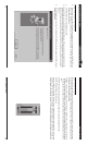
Direct Pro Host Port
The 25 pin port is reserved for the 6-foot cable included with the Direct
Pro 24/96. This connects directly with the 25 pin connector on the PCI
card. Note: Only the original cable should be used; damage may result
from using a different cable.
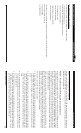
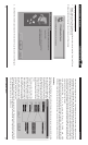
PCI Card
The PCI card houses S/PDIF ins and outs, and our DSP processor. Our shield-
ing process, along with the powerful DSP engine prevents unwanted com-
puter noise in your audio.
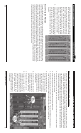
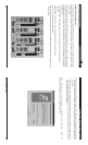
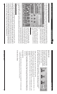
These faders can boost or cut the volume of the incoming signal in the monitor mix. It does not affect the
actual input volume of the track unless the REC FX button is pressed (see REC FX below). At all times,
this fader adjusts the level of the track as it is being sent into the MONITOR bus.
The text box above the fader displays the actual fader value in dB. It can range from minus infinity (OFF)
to +6 dB gain. If you would like no gain at this stage, just set this fader so the text box reads 0.0 dB.
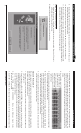
DIGITAL PEAK METERS
These individual peak meters at all times show the value of the signal that is being sent to the computer
for recording. With one exception listed below, all of the meters are post-fader (meaning the value of the
meter is calculated after the fader) so moving the fader affects the value of the meter.
The text box above each meter displays the actual meter value in dB.
On the 4 input strip meters, the value of the meter at all times shows the level of the signal this is being
recorded to the computer. The meters on the 4 input strips can change in meaning when the REC FX
button is pressed. (read REC FX below)
On the 6 Playback meters, the value of the meter shows the level being routed to the MONITOR bus AND
the level of the Playback channels.
On the MONITOR digital peak meter, it shows the combined levels of all things routed to the MONITOR
bus.
PEAK & RESET
All of the above digital meters can be switched to Peak meters by pressing the ‘PEAK’ button below the
MONITOR meters in the bottom right hand corner of the Control Panel. This affects all the digital meters
on the Control Panel and can be reset by hitting the ‘RESET’ button next to the ‘PEAK’ button.
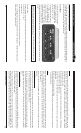
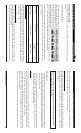
S/PDIF Digital I/O
S/PDIF (Sony/Phillips Digital Interface Format) allows a full 24 bit digital
connection to a DAT, CD player, or most any S/PDIF compatible unit. S/
PDIF ports are stereo, allowing a full stereo signal to pass through one S/
PDIF cable. We recommend using only professional S/PDIF cables for these
ports. To activate the S/PDIF inputs, go to the Direct Pro Control Panel. Click
on the Analog 3 In or Analog 4 In on the top of the Analog 3,4 channel strip. This changes the 3,4 input
to S/PDIF digital. The MIC/LINE 3,4 inputs will not record.
If you are recording via the S/PDIF input, be sure you have S/PDIF chosen in the Source Select section of
the Direct Pro control panel. Otherwise, jitter and unwanted noise may occur.
OUT
IN
➝
➝