


Guided Tour
X2 Reference Manual 13
CHAPTER 2:
GUIDED TOUR
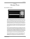
Recorder/Mix Systems
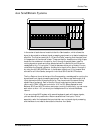
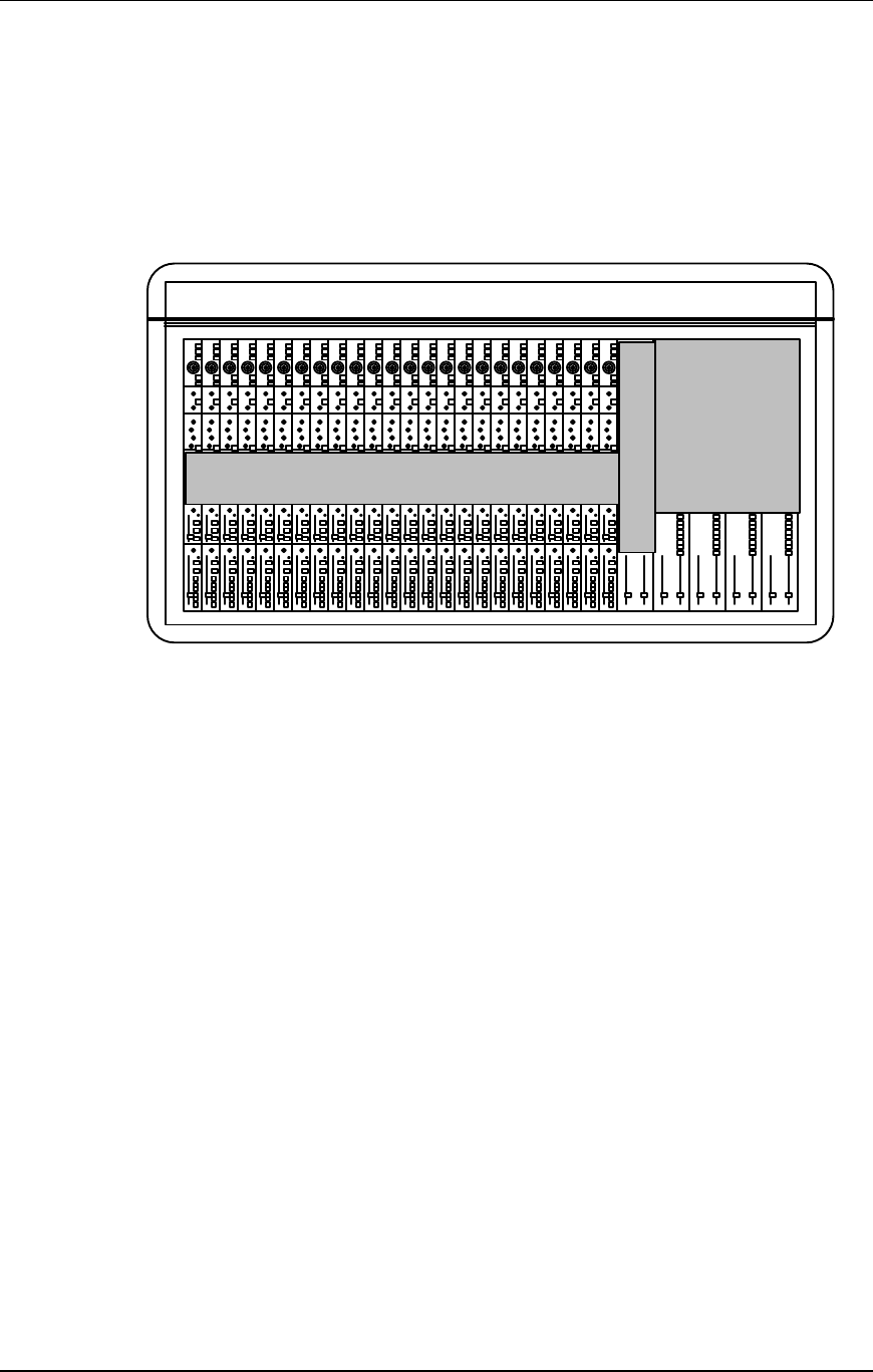
The X2 is designed to be extremely flexible, as evidenced by the channel module
design. This is where signals are mixed, EQ’d and routed to the Aux sends, Groups
and Left and Right Master outs. Each channel provides a Tape In connector, where
signals return from the multitrack recorder. These can be routed to either the main
or monitor section of the channel. This allows you to mix a signal and monitor a
tape signal simultaneously. If you also count the Aux returns, you have a total of 64
inputs. These can all be mixed down to a master tape deck via the L-R Master outs.
Let’s trace the signal flow from beginning to end. Note that the controls from top to
bottom of each channel are not placed in the same order as they appear in the signal
flow. To see the paths of the signal flow, refer to the block diagram accompanying
this manual.
Each input module has three possible sources (line, mic and tape in) and two paths
(the main channel and the monitor). First, the signal arrives at either the line or mic
input of a channel; you choose one of these using the MIC/LINE switch. If using the
mic input with a condenser microphone, the +48 V switch should be turned on to
provide phantom power. If necessary, the Ø (phase) switch can be used to invert the
signal’s phase. Next we come to the MIC/LINE GAIN knob, which is used to set the
initial level of the signal. It is important to set this level properly, since high levels
could lead to distortion and too low levels will cause noise (see Setting Levels).
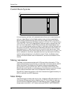
Each channel features an in-line monitor which sends either the tape return or the
input source to the L-R Master mix for monitoring. If we want to swap the inputs
between the main channel and the monitor, we just press the CHAN/MON
REVERSE button; now the tape returns are on the main channel while the normal