


Connecting the X2
22 X2 Reference Manual
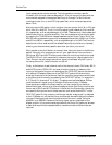
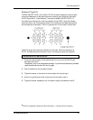
Channel Inputs and Outputs
Each of the 24 channel modules on the X2 contains an XLR balanced MIC Input
connector, a 1/4" TRS balanced LINE Input jack, a 1/4" TRS balanced TAPE IN jack
with a +4/-10 level switch, an unbalanced 1/4" TAPE SEND jack, and a TRS 1/4"
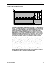
INSERT jack. Also included are three 56-pin ELCO connectors which provide eight
channels each of BALANCED TAPE Ins and Outs. Here are more detailed
descriptions of each of these, and what they should be connected to.
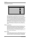
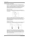
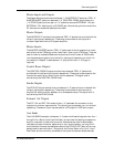
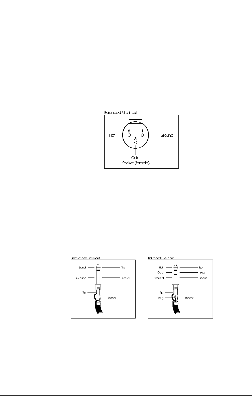
Balanced Mic Inputs
The MIC Input is a standard female XLR-3 connector and is available when the
MIC/LINE switch is in the MIC (out) position (see section 6.0.2). The cable wiring is
illustrated below
The MIC Input is designed to accept a wide range of balanced or unbalanced low
impedance input signals. Each Mic input can provide the +48V necessary for
phantom-powered microphones on pins 2 and 3; this may be turned on and off with
the [+48V] switch (see section 6.0.1). The phase of pins 2 and 3 may be reversed
using the [Ø] (phase) switch.
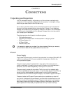
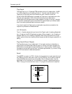
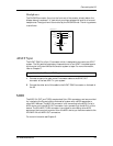
Unbalanced Line Inputs
The LINE Input is a 1/4" socket which will accept unbalanced or balanced line level
sources when the MIC/LINE switch (see section 6.0.2) is in the LINE position.
Unlike the low impedance microphone input, this connection provides a high
impedance (>10k) to the input signal, enabling many types of instruments to be
plugged straight in without direct boxes or external preamplification. While the
output of a standard synthesizer (or other equipment) can be plugged in using a 2-
conductor 1/4" plug, balanced line sources may also be connected here using a
“stereo” TRS plug as shown above.
Line inputs may also be used for connecting additional effects returns, where