30 Chapter 4—Getting Around the User Interface
01V—Owner’s Manual
Display Elements
This section explains the various control elements that appear on display pages.
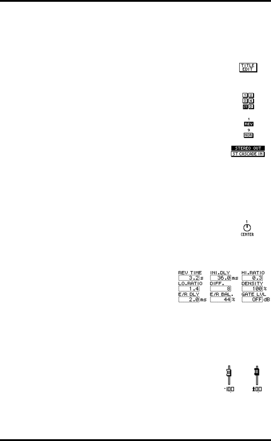
Switches
Switches appear as boxes with a shadowed outline (i.e., a thicker out-
line on the right side and bottom).
Simple on/off-type switches are highlighted when they are turned
on. In this example, the [ST] switch is on.
The labels inside some switches change when they turned on and
off, as these phase switches show.
For option-type switches, only one switch can be on at a time. In this
example, the monitor source can be set to either stereo out or ST
CASCADE IN, but not both.
To operate a switch, use the cursor buttons to select it, and the [ENTER] button or
[–1/DEC] and [+1/INC] buttons to turn it on or off.
Rotary Controls
Some parameters appear as rotary controls, as this example from
the PANPOT page shows. To adjust a rotary control, use the cursor
buttons to select it and use the PARAMETER wheel or [–1/DEC]
and [+1/INC] buttons to adjust it.
Parameter Boxes
Some parameters appear in parameter boxes
(i.e., dotted-line boxes), as this example from
the EFFECT1 EDIT page shows. To adjust a
parameter box parameter, use the cursor but-
tons to select it, and the PARAMETER wheel or
[–1/DEC] and [+1/INC] buttons to set it.
Parameter boxes that require you to confirm
new settings flash until you press the [ENTER]
button.
Faders
Pages such as VIEW and BUS MASTER display faders graphi-
cally. To adjust a fader, use the cursor buttons to select it, and the
PARAMETER wheel or [–1/DEC] and [+1/INC] buttons to set
it. Fader knobs appear highlighted when set to the nominal posi-
tion.


