


50 Chapter 5—Input Channels
01V—Owner’s Manual
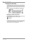
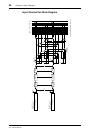
shows how it works.
The Routing switches on input channels 13 and 14 (likewise 15 and 16) are perma-
nently linked. When input channels 1 through 12 are paired (“Pairing Input Channels”
on page 52), their Routing switches are not linked.
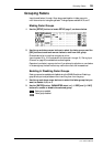
Monitoring Input Channels
Input channels can be monitored using the monitor out or phones. See “Monitor
Setup” on page 78 for more information.
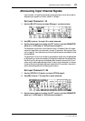
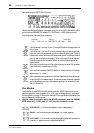
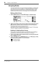
Input Channels & Aux Sends
Signals from input channels 1 through 16 can be sent to aux sends 1 through 4, while
those from input channels 17 through 24 can be sent to aux sends 1 and 2. Input chan-
nel sends can be configured as either pre-fader or post-fader sends. When aux sends are
paired, aux send panpots become available on each input channel. See “Aux Sends” on
page 93 for more information.
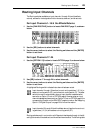
Input Channels & the Omni Outs
Direct signals from input channels 1 through 16 can be selected for the omni outs. See
“Omni Outs” on page 115 for more information. Note that OMNI OUTs are not
affected by the D switches on the PAN/ROUT page 2.
Input Channels & the Option I/O Outs
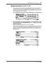
Input channels 1 through 16 can be selected as sources for the Option I/O outs. See
“Routing Input Channels” on page 49 and “About Option I/O Cards” on page 216 for
more information.
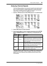
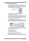
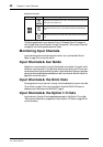
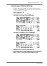
Routing Pan Signal Destination
Signals are fed equally to bus outs 1 and 2 and the left and right
channels of the stereo out.
Signals are fed to bus out 1 and the left channel of the stereo
out.
Signals are fed to bus out 2 and the right channel of the stereo
out.