Metering Signal Levels 83
01V—Owner’s Manual
Metering Signal Levels
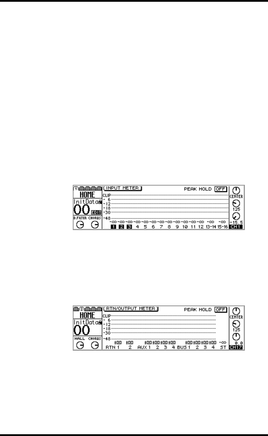
Signal level meters for input channels 1 through 16, the effects returns, aux sends, bus
outs, omni outs, and stereo output are provided on the HOME pages. The signal source
points for input and output meters can be set on HOME page 5. Stereo output levels
can be metered using the main stereo meters or the meters on HOME page 4. A Peak
Hold function can be set globally for all meters. Meters for input channels 17 through
24 and the eight digital outputs (Option I/O) are available on the OPTION pages. All
meters feature a CLIP indicator, which lights up when signals clip. If this happens, back
off the levels, otherwise signal distortion may occur.
Input channels 1 through 16, the stereo output, aux sends, and effects sends can also be
metered on the VIEW pages.
1. Use the [HOME] button to locate the following HOME pages.
Input channels 1–16
HOME page 1 displays signal level meters for input channels 1 through 16. The decibel
value below each meter indicates the position of the corresponding channel fader. The
highlighted numbers 1, 2, and 3 indicate that input channels 1, 2, and 3 have been
swapped with input channels 17, 18, and 19. See “Swapping Inputs 1–8 & 17–24” on
page 51 for more information.
Meters for input channels 1 through 16 also appear on the VIEW pages. See “Viewing
Input Channel Settings” on page 57 for more information.
Effects Returns, Aux Sends & Bus Outs
HOME page 2 displays signal level meters for the effects returns, aux sends, and bus
outs. The decibel value below each meter indicates the position of the corresponding
fader. The position of the stereo fader (ST) is also shown.
Meters for the effects returns also appear on the EFFECT and VIEW pages. See “Using
the Effects” on page 123 and “Viewing Effects Returns Settings” on page 130. Meters for
the aux sends also appear on the VIEW pages. See “Viewing Aux Send Settings” on page
98 for more information.


