


Control panel
12
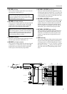
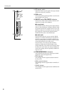
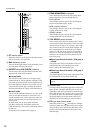
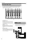
N ST (stereo) switch
When this switch is on, the signal of the input channel
will be sent to the (ST) stereo bus.
O BAL (balance) control
This sets the left/right balance of the signal that is sent
from the input channel to the ST bus.
P ON/EDIT switch/ON, CHECK indicators
The function of this switch and these indicators will
depend on the mode of the M3000A.
●In normal mode
The ON/EDIT switch will turn on the stereo input
channel. When on, the ON indicator will light. Chan-
nels which are turned off will send no signal to the ST
bus or the MIX buses. However even in this case, you
can use the PFL switch (T) to monitor the channel
from the MONITOR OUT jacks or the PHONE jack.
●In check mode
You can use the CHECK indicators to view the on/off
status of each channel stored in a scene before you
actually recall the scene. This is convenient when you
wish to verify the status of each channel before you
recall a scene.
In check mode, you can also use the ON/EDIT
switches to change only the lit/dark status of the
CHECK indicators. (The actual on/off setting will not
be affected.)
For details on Check mode, refer to page 33.
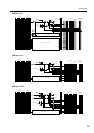
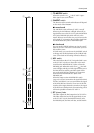
Q PEAK/NOM/SIGNAL indicators
Three indicators show the level of the stereo input
channel signal after it passes through the EQ.
• PEAK indicator
This will light when the sum of the L and R signals
exceeds the nominal level by 18 dB.
• NOM (nominal) indicator
This will light when the sum of the L and R signals
reaches nominal level (0 dB).
• SIGNAL indicator
This will light when the sum of the L and R signals
reaches 10 dB below the nominal level.
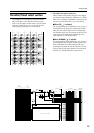
R VCA GROUP select switches
These switches select the VCA master fader(s) which
will control the signal output level of this stereo input
channel. When you select a VCA group 1–8, the indi-
cator located at the left of each switch will light, and
the corresponding VCA master fader (VCA master
section 3) will control the channel. It is possible to
select two or more VCA groups for one stereo input
channel, or to control two or more channels by the
same VCA group.
●Stereo input channels for which a VCA group is
selected
The signal output level of the channel can be con-
trolled both by the corresponding VCA master
fader(s) and by the channel fader (S).
●Stereo input channels for which a VCA group is
not selected
The signal output level of the stereo input channel can
be controlled only by the channel fader (S).
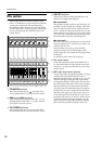
S Channel fader
This fader adjusts the signal output level of the stereo
input channel. This fader will affect the level of the
signal that is sent to the ST bus and to the MIX buses
(if the PRE switch is off). If one or more VCA groups
are selected by the VCA GROUP select switches (R),
the signal output level of that channel will also be
affected by the corresponding VCA master fader(s).
T PFL (pre-fader listen) switch
When this switch is on ( ), the indicator will light,
and the pre-fader/post-EQ signal of this stereo input
channel will be sent to the PFL bus, allowing it to be
monitored from the MONITOR OUT jacks or the
PHONES jack.
ST
ON/
EDIT
PFL
CHECK
ON
PEAK
NOM
SIGNAL
BAL
RL
1
2
3
4
5
6
7
8
VCA
10
5
0
5
10
20
30
40
50
60
O
S
N
P
R
T
Q
Note: For details on VCA functions, refer to
page 38.