


Control panel
16
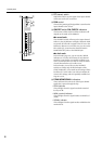
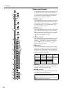
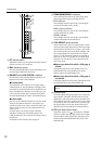
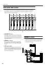
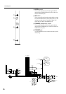
VCA master fader section
The VCA master fader section allows the gain of input channels assigned to a VCA group to
be controlled as a whole by the corresponding VCA fader. The VCA group(s) to which each
input channel is assigned is specified by the VCA GROUP select switches (mono input
channels (U), stereo input channels R).
A VCA MUTE switches
When these switches are turned on (the indicator at
left will light), the VCA master fader (3) will be shut
down completely. At this time, the post-fader signal of
all input channels assigned to the corresponding VCA
group will be muted.
B NOMINAL indicators
These indicators will light when the corresponding
VCA master fader is in the nominal (0 dB) position.
In this position, the VCA master fader will not affect
the gain.
C VCA master faders
These faders control the gain of the input channels
assigned to the corresponding VCA group. If you wish
to use the VCA master faders, make sure that the rear
panel VCA MASTER/SLAVE select switch (page 28) is
set to the MASTER position.
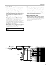
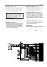
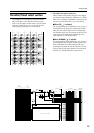
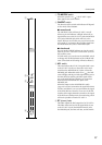
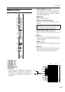
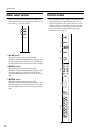
STEREO A section
This section controls the signal that is output from the
rear panel ST OUT jacks (page 27). The signal level
which is sent from ST OUT A to the matrix is also
controlled by this section.
MIX 13/14MIX 11/12 MIX 15/16
NOMINALNOMINAL
VCA
MUTE
VCA
MUTE
5
0
5
10
20
30
40
50
60
10
5
0
5
10
20
30
40
50
60
10
NOMINAL
VCA
MUTE
5
0
5
10
20
30
40
50
60
10
MIX 9/10
NOMINAL
VCA
MUTE
5
0
5
10
20
30
40
50
60
10
MIX 7/8
NOMINAL
VCA
MUTE
5
0
5
10
20
30
40
50
60
10
MIX 5/6
NOMINAL
VCA
MUTE
5
0
5
10
20
30
40
50
60
10
MIX 3/4
NOMINAL
VCA
MUTE
5
0
5
10
20
30
40
50
60
10
MIX 1/2
NOMINAL
VCA
MUTE
5
0
5
10
20
30
40
50
60
10
A
B
C
(SUB)(ST)
ON
ON/EDIT
CHECK ON
CONTROL
to Meter
to Meter
ON
AFL
TO MATRIX
AFL
PFL
LRON
MAS
AFL
MAS
LR
PFL
(MIX)
TO MATRIX
LEVEL
ST OUT B
L
R
ST
INSERT
I/O L
ST
INSERT
I/O R
R
L
ST OUT A
ST
RL
LR
1357
2468
9111315
10 12 14 16
LR
LR
to MONITOR OUT
to PHONES
AFL