


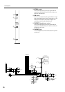
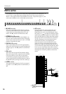
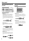


Rear panel
28
follows.
M MONITOR OUT jacks
These are XLR output jacks (balanced) for monitor-
ing the monitor source selected on the control panel.
Nominal output level is +4 dB. Pin wiring is as fol-
lows.
N 2TR IN jacks
These jacks are for connecting line-level external
devices.
●2TR IN 1 jacks
These are XLR balanced input jacks. Nominal input
level is +4 dB. Pin wiring is as follows.
●TR IN 2 jacks
These are 1/4" phone unbalanced input jacks. Nomi-
nal input level is –10 dBV. Pin wiring is as follows.
O ST SUB IN jacks
These are 1/4" phone jacks (unbalanced) for mixing
the signal from an external device into the ST bus.
Nominal input level is +4 dB. Pin wiring is as follows.
P CUE SUB IN jacks
These are 1/4" phone jacks (unbalanced) for mixing
the signal from an external device into the PFL bus.
Nominal input level is +4 dB. Pin wiring is as follows.
Q PHANTOM MASTER switch
This is the master switch for the +48V phantom
power supply.
R VCA EXTERNAL I/O connector
This connector can be connected to an external device
which has a VCA control function. This allows the
VCA control functionality of the other device to
which this connector is connected to be controlled
from a single console. If the M3000A is to be the mas-
ter for the VCA control, set the VCA MASTER/SLAVE
switch (N) to the MASTER position. If the M3000A is
to be the slave, set the VCA MASTER/SLAVE switch to
the SLAVE position. Pin wiring is as follows.
S VCA MASTER/SLAVE switch
When an external device with VCA control function-
ality is connected to the VCA EXTERNAL I/O connec-
tor, this switch determines whether or not the
M3000A will be the master for the VCA control. If the
M3000A is to be the VCA control master, set this
switch to the MASTER position. If the M3000A is to
be the slave, set this switch to the SLAVE position.
T CUE CONTROL jack
When using two M3000A consoles, connect their
respective CUE CONTROL jacks with a standard
unbalanced shielded cable. If this is done, turning on
the PFL switch of one M3000A to select the PFL bus as
the monitor source will allow you to monitor the PFL
bus of the other console as well.
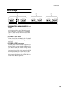
Female XLR plug
1 (ground)
3 (cold)
2 (hot)
Female XLR plug
1 (ground)
3 (cold)
2 (hot)
Male XLR plug
1 (ground)
3 (cold)
2 (hot)
1/4" phone plug
Tip (send)
Sleeve (ground)
1/4" phone plug
Tip (send)
Sleeve (ground)
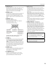
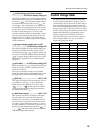
Pin# Assignment
1 VCA control 1
2 VCA control 2
3 VCA control 3
4 VCA control 4
5 VCA control 5
6 VCA control 6
7 VCA control 7
8 VCA control 8
9 Ground
1/4" phone plug
Tip (send)
Sleeve (ground)