


Control panel
21
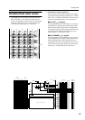
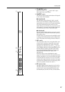
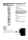
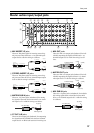
Talkback section
A M1–M2 switch
B M3–M4 switch
C M5–M6 switch
D M7–M8 switch
E M9–M12 switch
F M13–M16 switch
G ST switch
These switches send the talkback or test tone oscillator
signal to MIX buses 1–2, MIX buses 3–4, MIX buses
5–6, MIX buses 7–8, MIX buses 9–12, MIX buses 13–
16, or the ST bus. The switches can be turned on/off
individually.
H OSCILLATOR select switch
These switches select the type of test oscillator, and
begin oscillation. Only one can be selected at a time.
The corresponding indicator will light to indicate the
switch which is currently on.
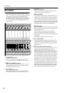
●PINK switch
Pink noise will be produced.
●10 kHz/1 kHz/100 Hz switches
A sine wave of the corresponding frequency will be
produced.
I OSCILLATOR OFF/ ON switch
This is an off/on switch for the oscillation of the oscil-
lator.
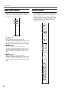
J MIC jack
This is an XLR-3-31 input jack (unbalanced) for con-
necting a talkback mic. It can be used with mics of 50–
600 ohms impedance.
K LEVEL control
This control adjusts the level of talkback or the oscilla-
tor.
L ON switch
This switch turns talkback on/off. When this is on, the
indicator located above the switch will light. If you
wish to use the oscillator, turn this switch off.
TALKBACK
MIC
OSCILLATOR
100Hz
1kHz
10kHz
PINK
ST
M13-M16
M1-M2
M3-M4
M9-M12
M7-M8
M5-M6
ON
LEVEL
100
A
B
C
D
E
F
G
I
J
K
L
H
ON
OFF/
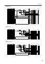
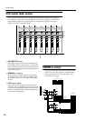
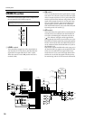
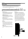
Note: The oscillator cannot be used in conjunction
with talkback. In order to use the oscillator, you
must turn off the talkback ON switch (L).
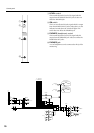
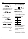
ST
LEVEL
BA
OFF/.ON
MIC HA
ST
LR
MIX
(FIX)
MIX
(VARIABLE)
1 3 5 7 12345678
2468
9111315
10 12 14 16
M1-M2
M3-M4
M5-M6
M7-M8
M9-M12
M13-M16
from Osillator